Quick Reference Instruction Manual
Wiring
Connecting cable
32 / 54
IM01U10A00-00EN-R, 2nd edition, 2017-08-29
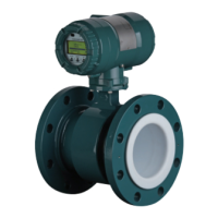
Fig.16: Connection terminal circuits (transmitter on the left side, sensor on the right side)
1 Driver circuit 4 Signal grounding
2 Sensor circuits 5 Transmitter
3 Temperature measurement circuits 6 Sensor
7.3 Connecting cable
With remote type flow meters, sensors and transmitters are connected by means of con-
necting cables.
In order to obtain optimum measuring results and ensure compliance with the specifica-
tion, it is imperative that an original connecting cable from Rota Yokogawa is used. In or-
der to ensure the IP code, the cable must be professionally installed at the entries using a
cable gland. If necessary, the cable may be shortened using the enclosed assembly kit.
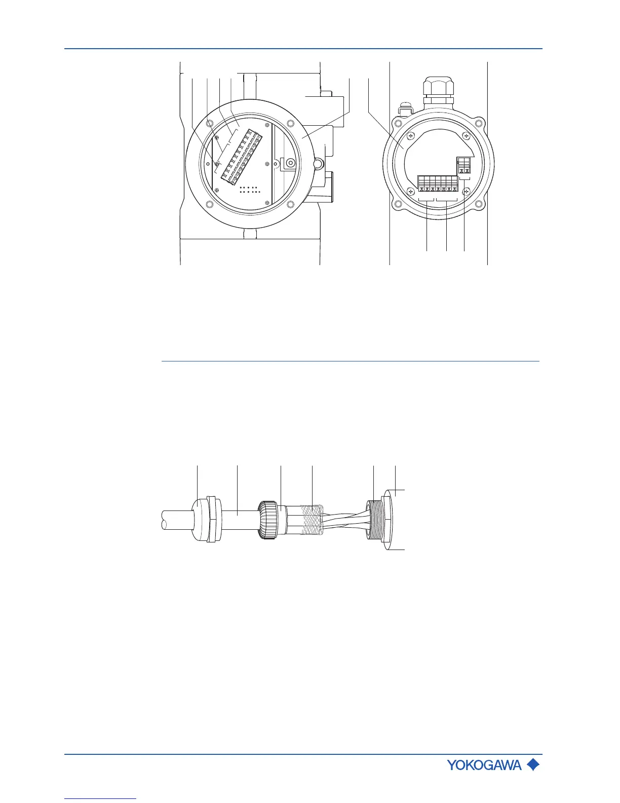
Fig.17: Structure of connecting cable
1 Cap 4 Outer cable shield
2 Connecting cable 5 Screw part
3 Clamp part 6 Housing cable entry
If the connecting cable included in the delivery is too short, additional lengths can be pro-
cured through the Yokogawa sales organization.
 Loading...