Page 5
Installation, Operation & Maintenance Manual ( IOPCKKS60220510C1)
LOCATION
Use the following guidelines to select a suitable location for these
units :
1. Unit are designed for outdoor installation only.
2. Condenser coils must have an unlimited supply of air.
3. Where a choice of location is possible, position the unit on
either north or east side of building.
4. For ground level installation, use a level concrete slab. The
length and width should be at least 6 inches greater than the
unit base rails. Do not tie slab to the building foundation.
5. Roof structures must be able to support the weight of the unit
and its options and/or accessories. Unit must be installed on
a solid level roof curb.
6. Maintain level tolerance to 1/2 inch maximum across the
entire length or width of the unit.
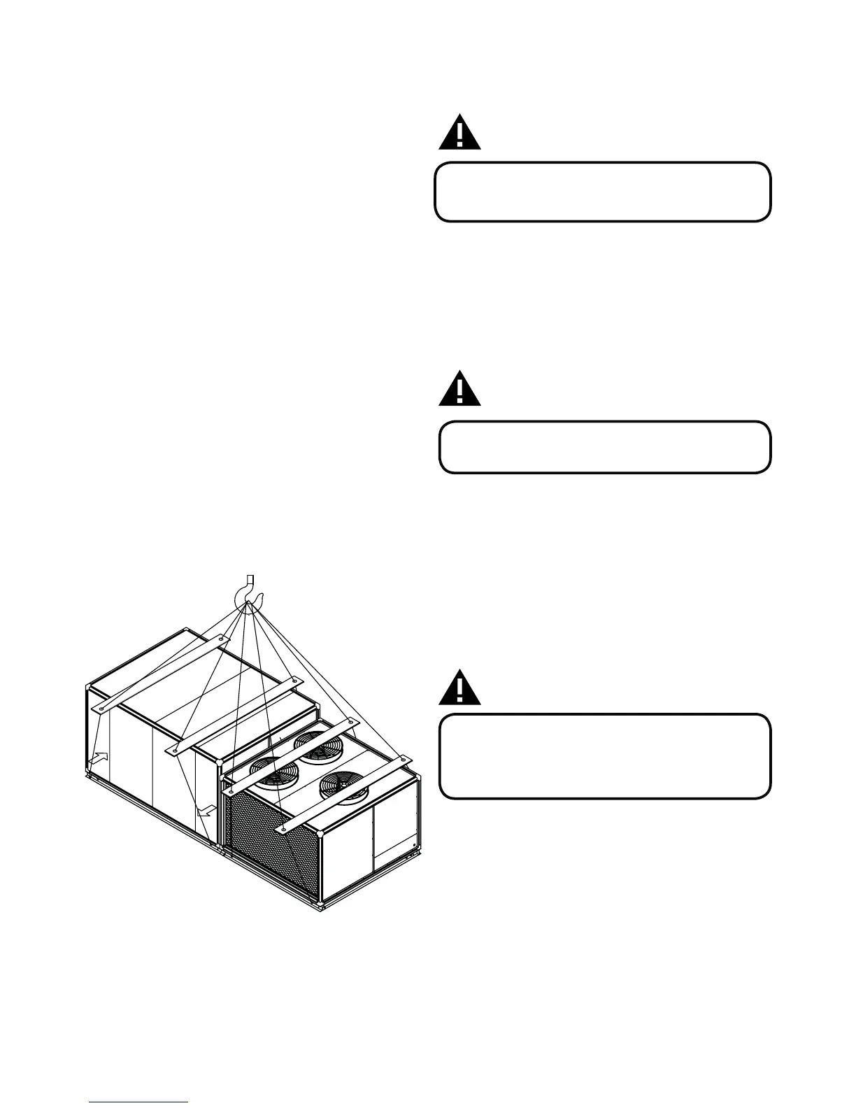
RIGGING AND HANDLING
Exercise care when moving the unit. Do not remove any packaging
until the unit is near the place of installation. Rig the unit by
attaching chain or cable slings to the round lifting holes provided
in the base rails. Spreaders, whose length exceeds the largest
dimension across the unit, MUST BE USED. Refer to Figure 2. Units
may also be moved or lifted with a forklift, from the side only,
provided that an accessory skid is used.
LENGTH OF FORKS MUST BE A MINIMUM OF 90”. Refer to the
Product Data Table 5 for unit weights.
Figure 2: Typical Rigging
WARNING
BEFORE LIFTING A UNIT, MAKE SURE THAT ALL PANELS
ARE IN PLACE AND THAT ITS WEIGHT IS DISTRIBUTED
EQUALLY ON ALL CABLES SO IT WILL LIFT EVENLY
CLEARANCES
All units require certain clearances for proper operation and
service. Installer must make provisions for adequate ventilation
air in accordance with applicable provisions of the local building
codes. Refer to Dimensions and Clearances. Refer Figure 8 for the
clearances required for servicing, and proper unit operation.
WARNING
DO NOT PERMIT OVERHANGING STRUCTURES OR
SHRUBS TO OBSTRUCT OUTDOOR AIR DISCHARGE
OUTLET.
DUCTWORK
A closed return duct system should be used. This should not
preclude use of outdoor fresh air intake.
The supply and return air duct connections at the unit should
be made with flexible joints to minimize noise. The supply and
return air duct systems should be designed for the CFM and static
requirements of the job. They should NOT besized to match the
dimensions of the duct connections on the unit.
WARNING
WHEN FASTENING DUCTWORK TO SIDE DUCT FLANGES
ON UNIT, INSERT SCREWS THROUGH DUCT FLANGES
ONLY. DO NOT INSERT SCREWS THROUGH CASING.
OUTDOOR DUCTWORK MUST BE INSULATED AND
WATERPROOFED.
Refer to Dimensions and Clearances Figure 7 for information
concerning supply and return air duct openings.
FIXED OUTDOOR AIR INTAKE DAMPER
This damper is shipped inside the return air compartment. It is
completely assembled and ready for installation. Refer to the
Fixed Outdoor Damper Figure 3.
Gasketing and mounting screws are provided in a parts bag.
Adjusting the damper to the desired air flow may be done after
installation by opening or closing dampers with handle.
Damper provides maximum of 25% fresh air when fully opened.
 Loading...