Page 7
Installation, Operation & Maintenance Manual ( IOPCKKS60220510C1)
COMPRESSORS
Units are shipped with factory adjusted compressor mountings
and ready for operation.
CAUTION
DO NOT LOOSEN COMPRESSOR MOUNTING BOLTS.
REMOVE COMPRESSOR SHIPPING BRACKETS BEFORE
START-UP.
FILTERS
Two inch filters can be supplied with each unit. Filters must always
be installed ahead of the evaporator coil and must be kept clean
or replaced with same size and type. Dirty filters will reduce
the capacity of the unit and will result in frosted coils or safety
shutdown. Minimum filter area and required sizes are shown in
Product Data Table 4.
SERVICE ACCESS
The following removable panels provide access to all serviceable
components :
t Compressor compartment
t Electric Heat compartment
t Blower compartment
t Main control box
t Filter compartment
Refer to the Dimensions and Clearances Figure 7 for location of
these access panels.
THERMOSTAT
4 Stage Cooling
The room thermostat should be located on an inside
wallapproximately 56 inches above the floor where it will not
besubject to drafts, sun exposure or heat from electrical fixtures
or appliances. Follow manufacturers instructions enclosed with
thermostat for general installation procedure. A minimum of seven
color coded insulated wires (#18 AWG) should be used to connect
thermostat to unit.
POWER AND CONTROL WIRING
Field wiring to the unit must conform to provisions of the National
Electrical Code and/or local ordinances. The unit must be electrically
grounded in accordance with NEC and/or local codes.
Voltage tolerances, which must be maintained at the compressor
terminals, during starting and running conditions, are indicated on
the unit Rating Plate and the Unit Application Data table.
A fused disconnect switch should be field provided based on the
tabulated rating, with a short circuit capacity of 10K or more, for
the unit. The switch must be separate from all other circuits. Wire
entry at knockout openings require conduit fittings to comply with
local codes. Refer to the Dimensions and Clearances Figures 8 for
installation location.
If any of the wire supplied with the unit must be replaced,
replacement wire must be of the type shown on the wiring diagram
and the same minimum gauge as the replaced wire.
Electrical line must be sized properly to carry the load. Use copper
conductors only. Each unit must be wired with a separate branch
circuit fed directly from the meter panel and properly fused.
Emergency stop button should be field installed as per wiring
diagram. The activator should be red in colour with a yellow outline
background, and should be easily accessible. The device should
be self latching type and contacts must be of positive opening
operation, certified to EN60947 - 5 - 1.
CAUTION
WHEN CONNECTING ELECTRICAL POWER AND CONTROL
WIRING TO THE UNIT, WATERPROOF TYPE CONNECTORS
MUST BE USED SO THAT WATER OR MOISTURE
CANNOT BE DRAWN INTO THE UNIT DURING NORMAL
OPERATION. THE ABOVE WATERPROOFING CONDITIONS
WILL ALSO APPLY WHEN INSTALLING A FIELD SUPPLIED
DISCONNECT SWITCH.
Refer to Typical Wiring Diagram, Figure 7 and to the appropriate unit
wiring diagram for control circuit and power wiring information.
Wire Size Maximum Length (1)
18 AWG 150 feet
From the unit to the thermostat and back to the unit
Table 2: Control Wire Sizes
OPTIONAL ELECTRIC HEAT
The factory installed heaters are wired for single point power
supply. Power supply need only be brought into the singlepoint
terminal block and thermostat wiring to the low voltage terminal
strip located in the upper portion of the unit control box.
These heaters are located within the supply air chamber.Refer
to Figure 8 for access panel location. Fuses are supplied by the
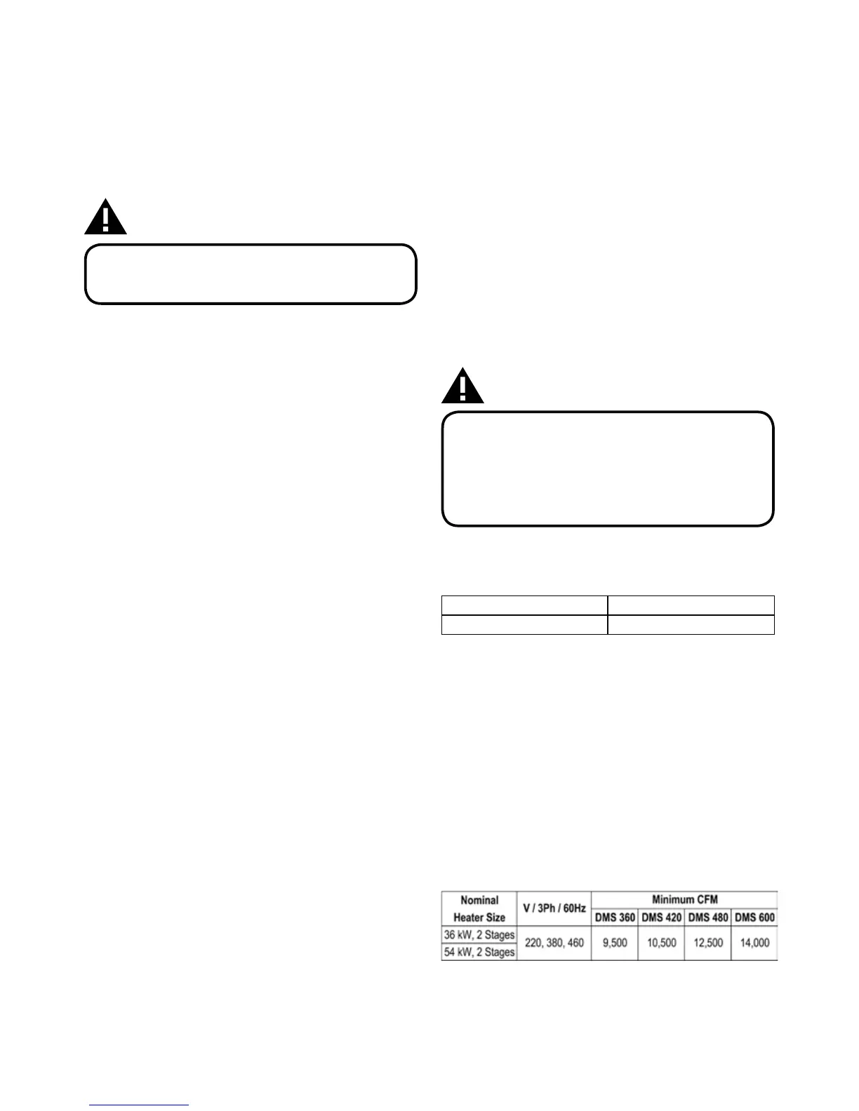
factory. Refer to Table 3 for minimum CFM limitations and to Table
5 for electrical data.
Table 3: Minimum CFM Limitation
 Loading...