5169032-UIM-C-0416
18 Johnson Controls Unitary Products
SECTION XIII: MAINTENANCE
Filters must be cleaned or replaced when they become dirty. Inspect at
least once per month. The frequency of cleaning depends upon the
hours of operation and the local atmospheric conditions. Clean filters
keep unit efficiency high.
COIL CLEANING
If the coil needs to be cleaned, it should be cleaned with water.
LUBRICATION
The bearings of the blower motor are permanently lubricated.
CONDENSATE DRAINS
During the cooling season check the condensate drain lines to be sure
that condensate is flowing from the primary drain but not from the
secondary drain. If condensate ever flows from the secondary drain the
unit should be promptly shut off and the condensate pan and drains
cleaned to insure a free flowing primary drain.
SECTION XIV: AIR SYSTEM ADJUSTMENT
To check the Cubic Feet per Minute (CFM), measure the external duct
static using a manometer and static pressure tips. To prepare coil for
static pressure measurements run the fan only to assure a dry coil.
Drill 2 holes, one 12” away from the air handler in the supply air duct
and on 12” away from the air handler in the return air duct (before any
elbows in the duct work). Insert the pressure tips, and energize the
blower motor. See Table 9 to determine the air flow, and make the
necessary adjustments to keep the CFM within the airflow limitations of
the coil.
EXTERNAL DUCT STATIC
Measure the supply air static pressure. Record this positive number.
Measure the return air static pressure. Record this negative number.
Treat the negative number as a positive, and add the two numbers to-
gether to determine the total external system static pressure. If a filter
rack is installed on the return air end of the air handler or indoor coil sec-
tion, make sure to measure the return air duct static between the filter
and the indoor coil.
48C
#5 HI 1759 1719 1685 1644 1611 1578 1540
#4 MED-HI 1684 1639 1606 1569 1536 1489 1452
#3 MED 1511 1460 1427 1388 1347 1308 1262
#2 MED-LO 1305 1260 1212 1178 1121 1076 1027
#1 LO 1123 1068 1029 985 909 793 769
48D
#5 HI 1774 1726 1684 1651 1614 1574 1529
#4 MED-HI 1709 1668 1619 1580 1548 1499 1459
#3 MED 1484 1436 1410 1372 1321 1284 1237
#2 MED-LO 1295 1254 1218 1167 1114 1069 1005
#1 LO 1102 1051 1011 962 890 831 766
60C
#5 HI 1964 1930 1897 1858 1823 1789 1752
#4 MED-HI 1889 1855 1818 1791 1747 1716 1668
#3 MED 1693 1652 1627 1584 1551 1510 1462
#2 MED-LO 1486 1450 1411 1375 1335 1291 1252
#1 LO 1292 1247 1207 1172 1123 1055 990
60D
#5 HI 1907 1871 1835 1796 1762 1723 1681
#4 MED-HI 1851 1816 1774 1742 1699 1659 1616
#3 MED 1648 1608 1569 1530 1492 1445 1404
#2 MED-LO 1456 1416 1371 1333 1289 1227 1163
#1 LO 1261 1221 1172 1120 1055 998 949
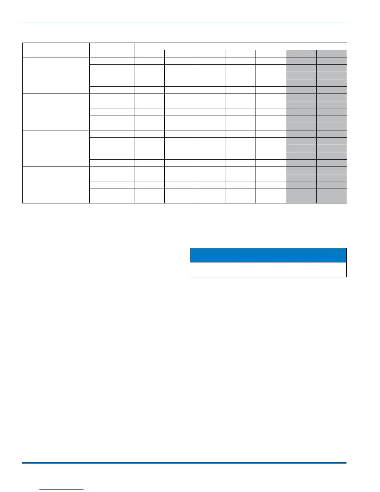
1. Air handler units have been tested to UL 1995 / CSA 22.2 standards up to 0.50" wc. external static pressure.
Dry coil conditions only, tested without filters.
For optimal performance, external static pressures of 0.2" to 0.5" are recommended. Applications above 0.5" are not recommended.
Airflow data shown is from testing performed at 230V. AE units use a standard ECM constant torque motor, and there is minimal variation of airflow at other distribution
voltage values. The above data can be used for airflow at other distribution voltages.
TABLE 11:
Air Flow Data (CFM)
1
Models
Blower
Motor Speed
External Static Pressure (in. wc.)
0.10 0.20 0.30 0.40 0.50 0.60 0.70
NOTICE
Refer to Table 11 for coil Air Flow Data of Cubic Feet Per Minute
(CFM).

 Loading...