5169032-UIM-C-0416
2 Johnson Controls Unitary Products
SAFETY REQUIREMENTS
1. Failure to carefully read and follow all instructions in this manual
can result in air handler malfunction, death, personal injury and/or
property damage.
2. This air handler should be installed in accordance with all national
and local building/safety codes and requirements, local plumbing
or wastewater codes, and other applicable codes.
3. This air handler should be installed only in a location and position
specified in the “Unit Installation” section of this Instruction Man-
ual.
4. The air handler is not to be used for temporary heating of buildings
or structures under construction.
5. Always install the air handler to operate within the air handler’s
intended maximum outlet air temperature.
6. The unit rating plate displays the air handler model number. The
unit dimensions for the supply air plenum are provided in Figure 3
and Table 1 of this Instruction Manual. The plenum must be
installed according to the instructions.
7. Clearance from combustible material is provided under “Clear-
ances” in the “Unit Installation” section.
8. It is necessary to maintain clearances for servicing. Access must be
allowed for electric heaters and blower.
9. The unit rating plate and power supply must be verified to ensure
that the electrical characteristics match.
10. Air handler shall be installed so the electrical components are pro-
tected from water.
11. Installing and servicing heating/cooling equipment can be hazard-
ous due to the electrical components. Only trained and licensed
personnel should install, repair, or service heating/cooling equip-
ment. Unlicensed service personnel can perform basic mainte-
nance functions such as cleaning and replacing the air filters. When
working on heating/cooling equipment, the precautions in the man-
uals and on the labels attached to the unit and other safety precau-
tions must be observed as applicable.
12. These instructions cover minimum requirements and conform to
existing national standards and safety codes. In some instances
these instructions exceed certain local codes and ordinances,
especially those who have not kept up with changing residential
and non-HUD modular home construction practices. These instruc-
tions are required as a minimum for a safe installation.
WARNING
Improper installation, adjustment, alteration, or maintenance may cre-
ate a condition where the operation of the product could cause per-
sonal injury or property damage. Refer to this manual for assistance,
or for additional information, consult a qualified contractor, installer, or
service agency.
CAUTION
This product must be installed in strict compliance with the installation
instructions and any applicable local, state, and national codes
including, but not limited to building, electrical, and mechanical codes.
!
!
CAUTION
DO NOT lift air handler by the cabinet braces. The cabinet braces are
held in place by the coil channels. The cabinet braces could become
disengaged from the cabinet causing the air handler to fall, potentially
causing injury or damaging property. See Figure 1 for location of cab-
inet braces. Lift the air handler by tightly gripping the casing.
CAUTION
These air handlers should be transported & handled in an upright,
upflow position. Failure to do so may result in unit damage and per-
sonal injury. Configuration conversions should be done at site of
installation.
!
!
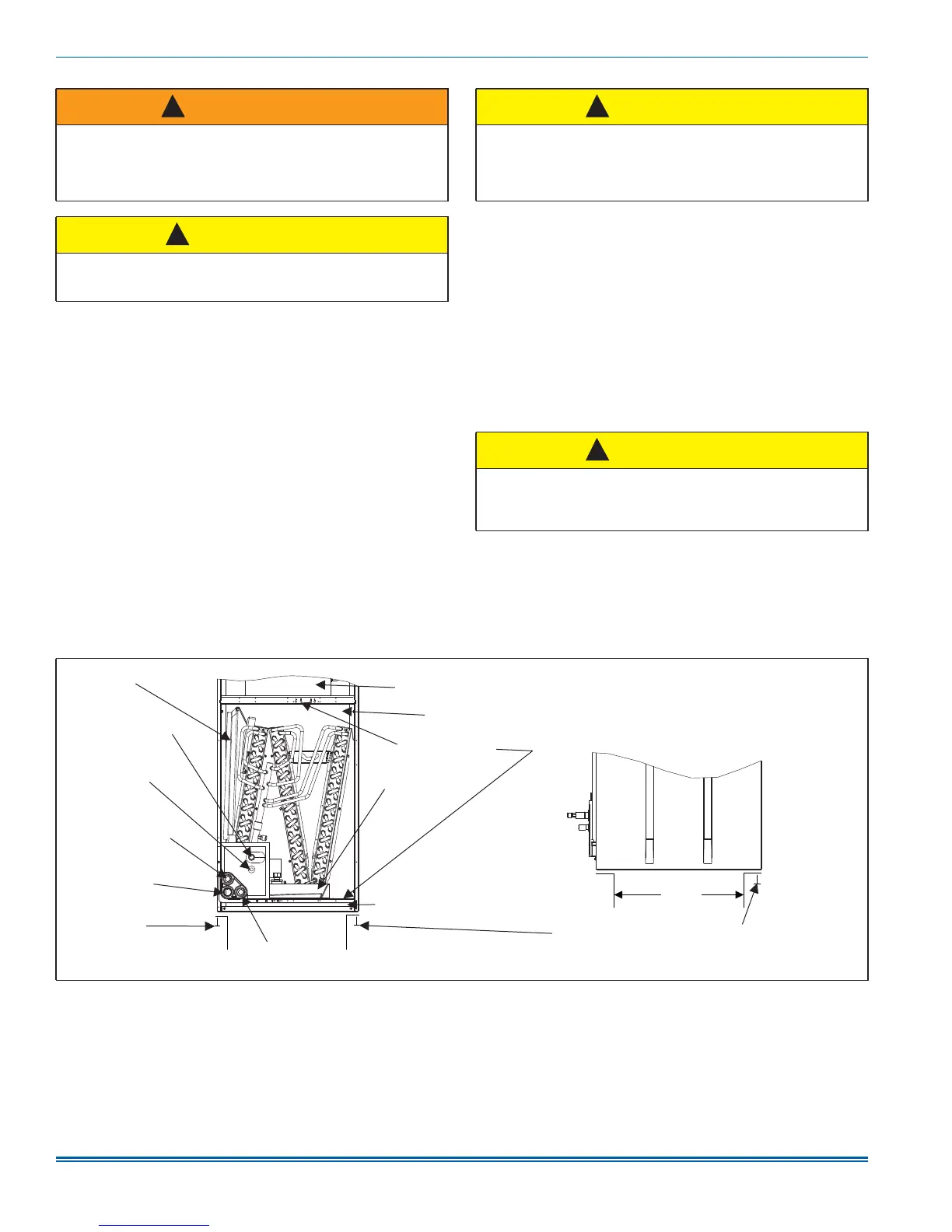
FIGURE 1: Return Air Duct Attachment & Component Location
SIDE VIEW
RETURN AIR
DUCT
FRONT VIEW
SECONDARY DRAIN
UPFLOW 3/4” NPT
FILTER DOOR
WHEN ATTACHING DUCTWORK WITH
SCREWS - KEEP SCREWS WITHIN 5/8”
OF SIDES AND BACK OF AIR HANDLER
DUCTWORK MAY
BE FASTENED
CAUTIOUSLY WITH
SCREWS TO THE
SIDES AND REAR OF UNIT
PRIMARY DRAIN
3/4” NPT
VAPOR
REFRIGERANT
LINE CONNECTION
LIQUID
REFRIGERANT
LINE CONNECTION
HORIZONTAL
DRAIN PAN
VERTICAL
DRAIN PAN
COIL COMPARTMENT
(Access panel removed)
BLOWER
COMPARTMENT
SECONDARY DRAIN
HORIZONTAL FLOW
3/4” NATIONAL PIPE
THREAD (NPT)
A0328-001
CABINET BRACES

 Loading...