EasyManua.ls Logo

York CZF024 THRU 060 User Manual

York CZF024 THRU 060
26 pages
To Next Page IconTo Next Page
To Previous Page IconTo Previous Page
Page #3 background imageLoading...
Page #3 background image
567175-YTG-E-0512
Johnson Controls Unitary Products 3
PROCEDURES:
1. Unit factory charge listed on the unit nameplate includes refrigerant for the condenser, the smallest evaporator, and 15 feet of interconnecting
line tubing.
2. Verify the TXV and additional charge required for specific evaporator coil in the system using the above table.
3. Additional charge for the amount of interconnecting line tubing greater than 15 feet at the rate specified in Physical and Electrical Data Table.
4. For TXV matches requiring additional charge, the refrigerant needs to be weighed in for specific coil match and lineset length.
5. Permanently mark the unit nameplate with the total system charge. Total System Charge = Base Charge (as shipped) + charge adder for
evaporator + charge adder for line set.
System Charge for Various Matched Systems
Outdoor Unit CZF02413(C) CZF03013(C) CZF03613(C) CZF04213(C) CZF04813(C) CZF06013(C)
Approved System Thermal Expansion Valve
1
4F1 4F1 4F1 4N1 4N1 4H1
Indoor Coil
2,3,4,5
TXV Kit - Additional Charge, Oz
AHE24B 9–––
AHE30B 90––
AHE36C 15 6 0
AHE42D –933
AHE48D 13 7 7 4
AHE60D 12 12 9 4
AHP30 90––
AHP36 –60–
AHP42 ––0–
AHP48 –––7 4
AHP60 –––7 4
AHR24B 9–––
AHR30B –0––
AHR36B –60–
AHR42C ––33
AHR48D –––7 4
AHR60D 12 9 4
AV*36 1560–
AV*48 ––77 4
AV*60 –––7 4 0
AHX24 4–––
AHX30 12 0
AHX36 15 6 0
AHX42 ––33
AHX48 ––77 4
AHX60 12 12 9 4
F6FP030 90––
F6FP036 90––
F6FP042 –933
F6FP048 13 7 7 4
F6FP060 12 12 9 4
F4FV060 ––77 4
FC/MC/PC32 90––
FC/MC/PC35 90––
FC/MC/PC37 15 6 0
FC/MC/PC43 15 6 0 0
FC/MC/PC48 –933 0
FC/MC/PC60 13 7 7 4 0
FC/MC62 12 12 9 4
FC64 18 18 15 11
HD48 ––33 0
HD60 ––77 4
UC48 –93– 0
UC60 13 7 7 4
Some of the combinations shown in the above System Charge table require Advanced Main Air Circulating Fan indoor product. For approved coil
only matches, please see the “COOLING CAPACITY - Upflow, Downflow & Horizontal Furnaces and Coils” table.
FOOTNOTES:
1. For applications requiring a TXV use S1-1TVM*** series kit.
2. Systems matched with furnace or air handlers not equipped with blower-off delays may require blower Time Delay Kit S1-2FD06700224.
3. PC coils cannot be used in downflow or horizontal applications. FC coils cannot be used in horizontal applications.
4. A TXV kit must be used with these coils to obtain system performance. Note: If a TXV is factory installed on the coil, it must be replaced wit the
listed TXV.
5. Refer to Cooling Performance Data tables for actual performance for specified system matches.
Question and Answer IconNeed help?

Do you have a question about the York CZF024 THRU 060 and is the answer not in the manual?

York CZF024 THRU 060 Specifications

General IconGeneral
BrandYork
ModelCZF024 THRU 060
CategoryAir Conditioner
LanguageEnglish

Summary

Product Description and Key Features

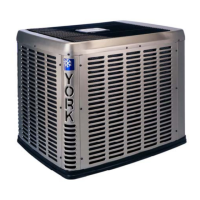
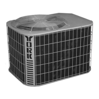
Product Description

Detailed explanation of the 16 SEER Series unit and its climate system capabilities.

Key Features

Highlights design elements and operational advantages of the Affinity™ Split-System Air Conditioners.

Superior Coil Protection

Metal guard protects the coil from debris and damage.

Isolated Compressor Compartment

Molded composite bulkhead isolates the compressor for reduced noise and vibration.

Protected Compressors

Internal pressure relief valve, high/low pressure controls, and liquid line filter driers protect compressors.

Environmentally Friendly Refrigerant

Uses R-410A refrigerant for environmentally friendly performance with zero ozone depletion.

Durable Finish

Automotive quality finish provides protection from UV rays and rust creep.

Low Operating Sound Levels

Fan design adapted from aerospace engineering ensures quiet operation.

Communications Capable

Simple 4-wire installation enables use with Touch Screen Communicating Control.

Physical and Electrical Data

Dimensions (Inches)

Lists the physical dimensions (A, B, C) for different outdoor unit models.

Refrigerant Connection Service Valve Size

Specifies the liquid and vapor service valve sizes for each outdoor unit model.

System Charge and Procedures

System Charge for Various Matched Systems

Details system charge requirements for different outdoor unit and indoor coil/furnace combinations.

Procedures

Step-by-step instructions for verifying and setting the correct system refrigerant charge.

Cooling Capacity - With Air Handler Coils

Cooling Capacity - With Air Handler Coils (Continued)

Cooling Capacity - With Air Handler Coils (Continued)

Cooling Capacity - Furnaces and Coils (Coil Only Ratings)

Cooling Capacity - With High Efficiency Motor Furnaces

Cooling Capacity - With High Efficiency Motor Furnaces (Continued)

Cooling Capacity - With High Efficiency Motor Furnaces (Continued)

Cooling Capacity - With High Efficiency Motor Furnaces (Continued)

Cooling Capacity - With High Efficiency Motor Furnaces (Continued)

Cooling Capacity - With High Efficiency Motor Furnaces (Continued)

Cooling Capacity - With High Efficiency Motor Furnaces (Continued)

Accessories and Installation

Accessories

Lists optional accessories like Hard Start Kits, TXV Kits, Low Ambient Pressure Switch Kit, and Thermostats.

Sound Power Level

Provides typical octave band spectrum sound power levels for different cooling modes and sizes.

Typical Installation

Illustrates a standard installation diagram with clearances and wiring notes.
Cooling Performance Data

Cooling Performance Data

Cooling Performance Data

Cooling Performance Data

Cooling Performance Data

Cooling Performance Data

Cooling Performance Data

Cooling Performance Data

Cooling Performance Data

Cooling Performance Data

Related product manuals