GB
Installation Instructions
Inspection
Upon reception, inspect the equipment and
notify both the carrier and the insurance
company, in writing, of any possible damage.
Environmental protection
Eliminate packing in accordance
with the regulations in force on
environmental conservation.
During installation and maintenance, keep
in mind that HFC-410A and oil POE are
used.
Contains greenhouse effect uorided
gas covered by the Kyoto protocol.
For the type of gas and quantity per system,
see the identication plate. GWP (Global
Warming Potential): 2088.
Safety
Installation and maintenance operations
of this air conditioning system should be
carried out only by qualied and expert
personnel.
Periodical maintenance operations should
be carried out, such as cleaning the coils and
air lters, so as to keep unit performance at
an optimum.
Caution
This unit should be installed and used in
accordance with:
- Low Voltage Electrotechnical
Regulations.
- Safety Regulations for Cooling
Plants and Installations.
- Regulations on Pressure Equipment.
- Basic Construction Standards.
- Technical Construction Standards.
- Local ordinances.
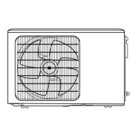
Location (Fig. 1 to 3)
To be installed directly outdoors. Place the
unit on a consistent base and fasten by
means of bolts.
Outdoor units
These units are supplied with an R-410A
refrigerant charge, which is sufcient for an
interconnecting piping length of 5 meters.
Each unit includes a connecting elbow for
the condensed water drain.
Installation
Unit installation comprises:
- Unit mounting.
- Refrigerant tubing connections.
- Condensed water drain connections in
heat pump units.
- Unit wiring.
Clearances, outdoor unit
A minimum clearance is required around
the units for the circulation of air and access
for maintenance servicing, as indicated in
the general dimensions.
Interconnection of the units
When installing Split units, the cooling
circuit should be completely leakproof after
mounting.
This will help to obtain maximum performance
with minimum consumption, and avoid serious
damage to the unit. This is an ecological
precaution as well.
Installation of interconnecting
pipes
The length of the interconnecting tubing of
the units should be as short as possible.
The maximum admissible distances with
regard to the circuit and standard tubing
diameters are indicated on each apparatus
of the corresponding indoor units.
Pipes to be used
Special care should be taken that the tubing
that interconnects the two units is kept
clean and dry, even prior to installation. It is
advisable to take into account the following
recommendations:
- Use copper refrigerant quality tubing
only.
- Do not work outdoors when raining.
- The ends of the tubing should remain
closed during installation.
- Do not leave dryer lters or the compressor
out in the open air.
- For welding use low melting point rods
with a 5% silver content, minimum.
- When welding and as long as the tubing is
hot, maintain a ow of dry nitrogen so as to
avoid internal rusting and scaling that could
cause contamination and obstructions.
- Do not use strippers on copper-copper
joints.
- Connection between units should be
carried out by means of the aring
method.
Insulation of refrigerant pipes
To avoid the inuence of outdoor
temperatures, radiation and condensation,
the pipes should be insulated. Minimum
thickness should be 8 mm.
Emptying and dehydrating
(Fig. 5)
Air does not act as a refrigerant since it
cannot be liqueed by the compressor.
Any air and humidity remaining in the
cooling system has undesirable effects, as
indicated below. Consequently, they should
be eliminated completely.
- High pressure increases.
- Consumed power supply increases.
- Equipment performance decreases.
- Water contained in the air could freeze
and block the capillaries.
- Water can cause corrosion of certain
parts of the circuit, and deterioration of
the compressor.
Process
In each circuit, with the valves closed:
1- Connect a vacuum pump and service
pressure gauges.
2- Carry out a vacuum of up to at least 200
microns.
3- Detect leaks.
Limits of use
Air intake temperature to outdoor coil DB Air intake temperature to indoor coil
Operating cycle Operating cycle
Minimum °C Maximum °C Minimum °C Maximum °C
Cool Heat Cool Heat Cool WB Heat DB Cool WB Heat DB
-10 -15 50 24 19 20
(1)
23 (1) 27
Notes: WB = Wet bulb. DB = Dry bulb.
(1) This equipment can operate at a temperature out of limits for a short period of time, until the occupied space is conditioned.
 Loading...