036-21083-007-A-0404
Unitary Products Group 7
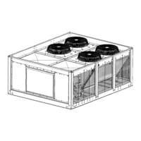
FIGURE 1 - TYPICAL FIELD WIRING WITH AIR HANDLER
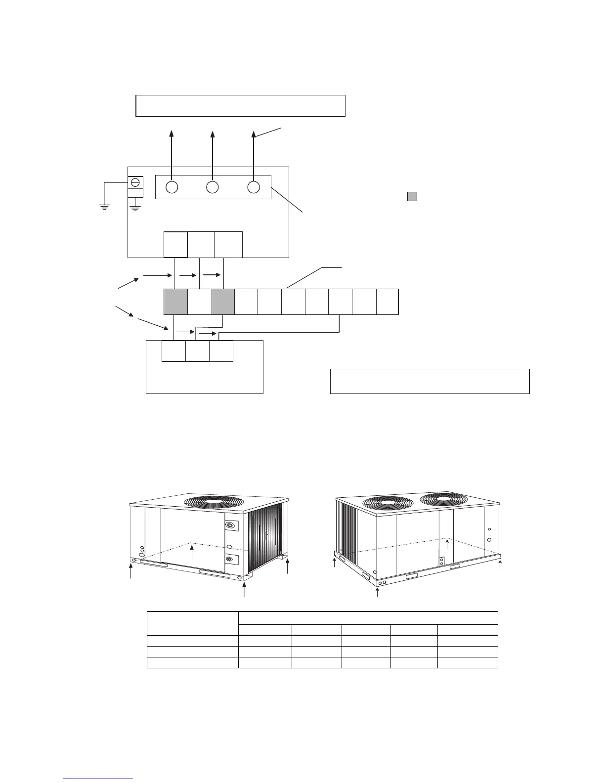
FIGURE 2 - 4 POINT LOADS
B
8
O
W
53 G 60 66
X
R
Y1
R
Y
G
R
Y
24 VOLT
TERMINALS ON BLOCK
TB1 OF BLOWER UNIT
FACTORY - MOUNTED
PIGTAILS ON TERMINAL
COMPRESSOR
CONTACTOR 1M
SIZE POWER WIRING
DICONNECT SWITCH, AND
FUSING PER ELECTRICAL
DATA TABLE
NOTE: USE COPPER CONDUCTORS ONLY
NOTE: Use thermostat 2HT04701424
if the blower unit is equipped
with a 2-stage electric
heat accessory.
Use thermostat 2TH07701024
if the blower unit is equipped
with a hot water coil, a steam coil
or a 1-stage electric heat
accessory.
The field wiring connected to these
dummy terminals on TB1 can be
unit to the thermostat if desired.
WIRE IN ACCORDANCE WITH ALL LOCAL
AND NATIONAL ELECTRICAL CODES
routed directly from the condensing
THERMOSTAT
2TH08701024
A
D
C
B
A
B
C
D
UNIT
4-POINT LOAD (lbs)
Total A B C D
090 360 60 70 124 106
120 430 90 114 127 99
150 510 111 152 143 104
HCE120 & 150HCE090

 Loading...