Physical and electrical data
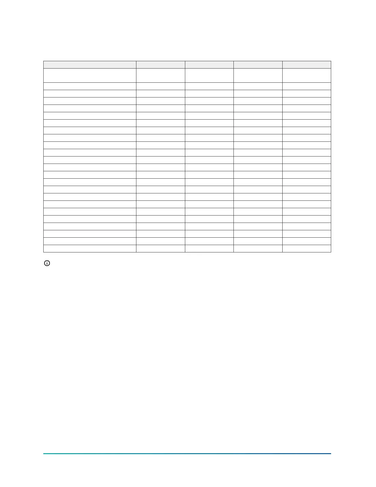
Table 2: Physical and electrical data
Model HMH72B241S HMH72B361S HMH72B481S HMH72B601S
Unit supply voltage 208/230 V, 1
phase, 60 Hz
208/230 V, 1
phase, 60 Hz
208/230 V, 1
phase, 60 Hz
208/230 V, 1
phase, 60 Hz
Normal voltage range (V) 198 to 253 198 to 253 198 to 253 198 to 253
Minimum circuit ampacity (A) 15 23 36 37
Maximum overcurrent device (A) 25 35 50 50
Minimum overcurrent device (A) 15 23 36 37
Compressor type Twin rotary Twin rotary Twin rotary Twin rotary
Compressor rated load (A) 11.0 16.1 26.0 26.5
Compressor locked rotor (A) n/a n/a n/a n/a
Crankcase heater (base heater) Yes Yes Yes Yes
Factory discharge muffler Yes Yes Yes No
HS kit required with TXV N/A N/A N/A N/A
Fan motor type ECM ECM ECM ECM
Fan motor quantity 1 1 2 2
Fan motor rated HP 1/12 1/6 1/6 1/6
Fan motor nominal RPM 880 810 850 850
Fan motor nominal CFM 1,825 2,350 3,525 3,525
Coil face area (sq. ft) 6.1 8.3 14.0 14.0
Coil rows deep 2 2 2 2
Coil fins per inch 18 19 17 18
Liquid lineset outdoor (field installed) 3/8 3/8 3/8 3/8
Vapor lineset outdoor (field installed) 5/8 3/4 7/8 7/8
Unit charge (lb-oz) 4-7 6-3 8-15 8-9
Charge (oz/ft) 0.38 0.38 0.60 0.60
Operating weight (lb) 112 157 227 251
Note:
• The normal voltage range is rated in accordance with AHRI Standard 110-2012, utilization
range A.
• Dual element fuses or HACR circuit breaker. Maximum allowable overcurrent protection.
• Dual element fuses or HACR circuit breaker. Minimum recommended overcurrent
protection.
• The unit charge provided is less than the system total charge required. Select the
appropriate indoor section and lineset length charge additions to calculate additional
charge required and total system charge.
• For applications with non-standard vapor line sizes, see Applications and accessories.
YORK Technical Guide: HMH7 Series - 17 SEER Horizontal Discharge Modulating Heat Pump8
Johnson Controls Ducted Systems
 Loading...