5803641-JIM-B-0620
40 Johnson Controls Ducted Systems
Air Balance
Start the supply air blower motor. Adjust the resistances in both
the supply and the return air duct systems to balance the air
distribution throughout the conditioned space. The job
specifications may require that this balancing be done by
someone other than the equipment installer.
Checking Air Quantity
Method One
1. Remove the dot plugs from the duct panel (for location of
the dot plugs see Figures 12 and 13).
2. Insert eight-inches of 1/4 inch metal tubing into the airflow
on both sides of the indoor coil.
NOTE: The tubes must be inserted and held in a position
perpendicular to the air flow so that velocity pressure
will not affect the static pressure readings.
3. Use an Inclined Manometer or Magnehelic to determine
the pressure drop across a dry evaporator coil. Since the
moisture on an evaporator coil can vary greatly, measuring
the pressure drop across a wet coil under field conditions
could be inaccurate. To assure a dry coil, the compressors
should be de-activated while the test is being run.
NOTE: De-energize the compressors before taking any test
measurements to assure a dry evaporator coil.
4. The CFM through the unit can be determined from the
pressure drop indicated by the manometer by referring to
Figure 28. In order to obtain an accurate measurement, be
certain that the air filters are clean.
5. To adjust Measured CFM to Required CFM, see.
6. After readings have been obtained, remove the tubes and
replace the dot plugs.
7. Tighten blower pulley and motor sheave set screws after
any adjustments. Re-check set screws after 10-12 hrs. run
time is recommended.
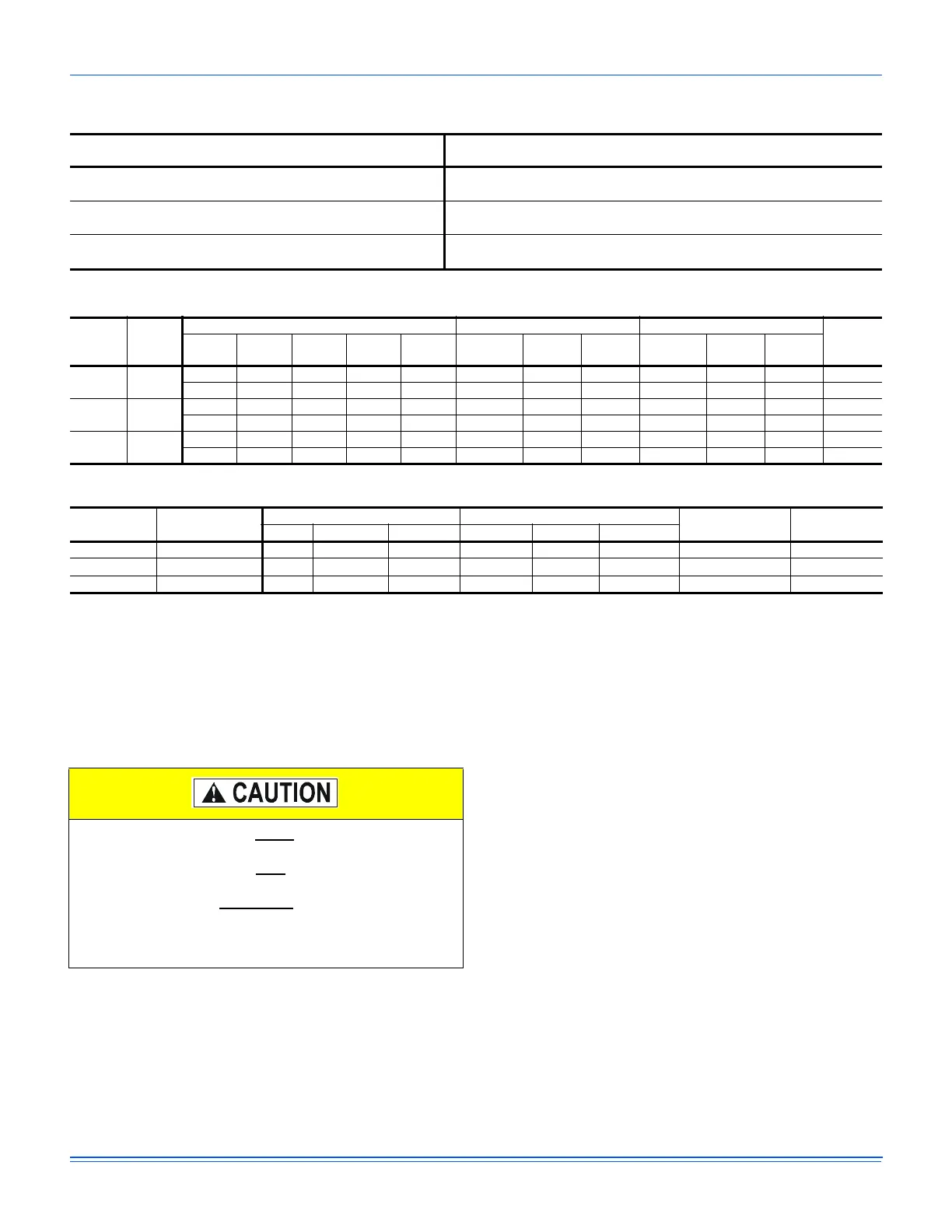
Table 19: RPM Selection
Size
(Tons)
Model HP
Max
BHP
Motor
Sheave
Blower
Sheave
6 Turns
Open
5 Turns
Open
4 Turns
Open
3 Turns
Open
2 Turns
Open
1 Turn
Open
Fully
Closed
JA3
(3)
ZJ
1.5 1.5 1VP34 AK69 N/A 531 584 637 690 743 796
1.5 1.5 1VL44 AK69 N/A 796 849 902 955 1008 1062
JA4
(4)
ZJ
1.5 1.5 1VP34 AK56 N/A 663 730 796 863 929 995
1.5 1.5 1VL44 AK56 N/A 995 1062 1128 1194 1261 1327
JA5
(5)
ZJ
1.5 1.5 1VL40 AK61 N/A 787 847 908 968 1029 1089
2 2 1VP56 BK74 N/A 1035 1084 1134 1183 1232 1281
Table 20: Indoor Blower Specifications
Size
(Tons)
Model
Motor Motor Sheave Blower Sheave
Belt
HP RPM Eff. SF Frame
Datum Dia.
(in.)
Bore (in.) Model
Datum Dia.
(in.)
Bore (in.) Model
JA3
(3)
ZJ
1-1/2 1725 0.8 1.15 56 2.0 - 3.0 7/8 1VM34 6.5 1 AK69 A47
1-1/2 1725 0.8 1.15 56 3.0 - 4.0 7/8 1VL44 6.5 1 AK69 A47
JA4
(4)
ZJ
1-1/2 1725 0.8 1.15 56 2.0 - 3.0 7/8 1VM34 5.2 1 AK56 A47
1-1/2 1725 0.8 1.15 56 3.0 - 4.0 7/8 1VL44 5.2 1 AK56 A47
JA5
(5)
ZJ
1-1/2 1725 0.8 1.15 56 2.6 - 3.6 7/8 1VL40 5.7 1 AK61 A47
2 1725 0.8 1.15 56 4.2 - 5.2 7/8 1VP56 7.0 1 BK74 A51
Table 21: Power Exhaust Specifications
Model Voltage
Motor Unit (Per Circuit)
Fuse Size
CFM @
0.1 ESP
HP RPM
1
1. Motors are multi-tapped and factory wired for high speed.
QTY LRA FLA MCA
2PE04704706 208/230-1-60 3/4 1075 1 24.9 5 6.3 10 4800
2PE04704746 460-1-60 3/4 1075 1 N/A 2.2 2.8 5 4800
2PE04704758 575-1-60 3/4 1050 1 N/A 1.5 1.9 4 4800
Belt drive blower systems MUST be adjusted to the
specific static and CFM requirements for the application.
The Belt drive blowers are NOT
set at the factory for any
specific static or CFM. Adjustments of the blower speed
and belt tension are REQUIRED
. Verify proper sheave
alignment; tighten blower pulley and motor sheave set
screws after these adjustments. Re-checking set screws
after 10-12 hrs. run time is recommended.
 Loading...