5803641-JIM-B-0620
Johnson Controls Ducted Systems 51
Adjustment Of Temperature Rise
The temperature rise (the difference of temperature between the
return air and the heated air from the furnace) must lie within the
range shown on the CSA rating plate and the data in Table 10.
After the temperature rise has been determined, the CFM can
be calculated as follows:
After about 20 minutes of operation, determine the furnace
temperature rise. Take readings of both the return air and the
heated air in the ducts (about 6 feet from the furnace) where
they will not be affected by radiant heat. Increase the blower
CFM to decrease the temperature rise; decrease the blower
CFM to increase the rise (See SUPPLY AIR DRIVE
ADJUSTMENT).
NOTE: Each gas heat exchanger size has a minimum
allowable CFM. Below this CFM, the limit will open.
Burners/Orifices Inspection/Servicing
Before checking or changing burners, pilot or orifices, CLOSE
MAIN MANUAL SHUT-OFF VALVE AND SHUT OFF ALL
POWER TO THE UNIT.
1. Open the union fitting just upstream of the unit gas valve
and downstream from the main manual shut-off valve in
the gas supply line.
2. Remove the screws holding each end of the manifold to the
manifold supports.
3. Disconnect wiring to the gas valves and spark igniter(s).
Remove the manifold & gas valve assembly. Orifices can
now be inspected and/or replaced.
To service burners, complete step 4.
4. Remove the heat shield on top of the manifold supports.
Burners are now accessible for inspection and/or
replacement.
NOTE: Reverse the above procedure to replace the
assemblies.
Make sure that burners are level and seat at the rear of the gas
orifice.
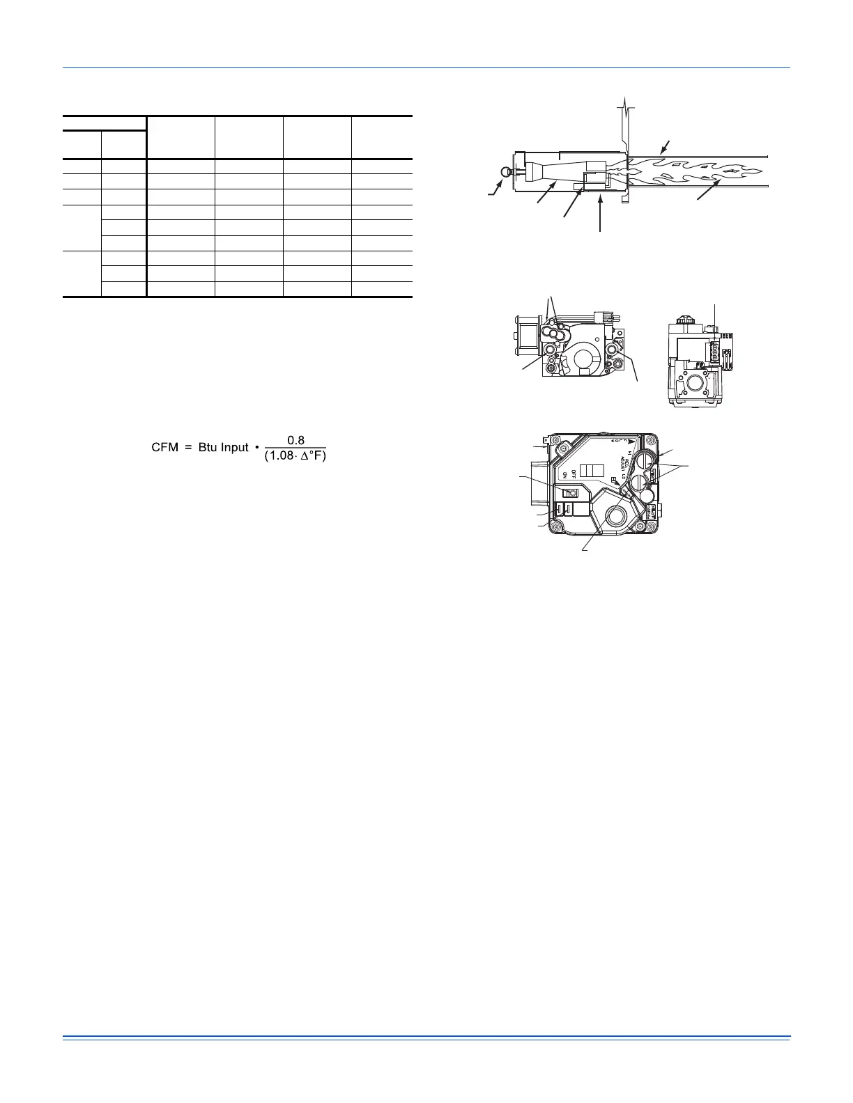
Figure 29: Typical Flame
Figure 30: Typical Two Stage Gas Valve
Charging The Unit
All J**ZJ units use Thermal Expansion Devices. Charge the unit
to nameplate charge.
Control Board Navigation Components
The following components are needed to access the control
points in the Smart Equipment™ control. Installation and
operation guides are available from your equipment dealer or
distributor.
1. Local LCD on Unit Control Board.
2. Mobile Access Portal (MAP) Gateway (Portable).
• Source 1 P/N S1-JC-MAP1810-OP
3. MAP Gateway Quick Start Guide P/N 24-10737-16
4. MAP Gateway Instruction P/N 24-10737-8
For more information on the Smart Equipment™ unit control board
navigation, refer to the Smart Equipment™ Quick Start Guide.
NOTE: For more in-depth sequence of operation of the Smart
Equipment™ control, refer to the Smart Equipment™
Controls Sequence of Operation Overview LIT-
12011950.
Table 28: Gas Heat Stages
Unit
# of Burner
Tubes
1st Stage
Input (Mbh)
2nd Stage
Input
(Mbh)
Total
Input
(Mbh)
Size Opt.
JA3 N06 4 45 15 60
N08 4 56 24 80
N12 6 84 36 120
JA4
N06 4 45 15 60
N08 4 56 24 80
N12 6 84 36 120
JA5
N08 4 56 24 80
N12 6 84 36 120
N16 8 112 48 160
HEAT EXCHANGER TUBE
BURNER FLAME
(BLUE ONLY)
IGNITOR
BURNER BRACKET
BURNER
GAS
SUPPLY
PIPE
INLET
PRESSURE
TAP
HIGH & LOW GAS ADJUSTMENT
OUTLET
PRESSURE
TAP
HI
LO
ON
OFF
MATE-N-LOCK
CONNECTORS
MV
C
HI
REGULATOR COVER SCREWS
(REG. ADJ. BENEATH THESE
SCREWS)
TERMINAL – HI (2ND STAGE)
ON/OFF SWITCH
C
MP
OUTLET PRESSURE TAP
INLET PRESSURE TAP
OR
TERMINAL – MP (1ST STAGE)
TERMINAL – C (COMMON)
 Loading...