YORK INTERNATIONAL 5
FORM 160.49-O2
7619A(D)
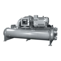
DETAIL A – COMPRESSOR PREROTATION VANES
design conditions. However, most systems will be called
upon to deliver full load capacity for only a relatively
small part of the time the unit is in operation.
CAPACITY CONTROL
The major components of a chiller are selected for full
load capacities, therefore capacity must be controlled to
maintain a constant chilled liquid temperature leaving
the cooler. Prerotation vanes (PRV), located at the en-
trance to the compressor impeller, compensate for varia-
tion in load (See Fig. 2. Detail A).
The position of these vanes is automatically controlled
through a lever arm attached to an electric motor lo-
cated outside the compressor housing. The automatic
adjustment of the vane position in effect provides the
performance of many different compressors to match
various load conditions from full load with vanes wide
open to minimum load with vanes completely closed.
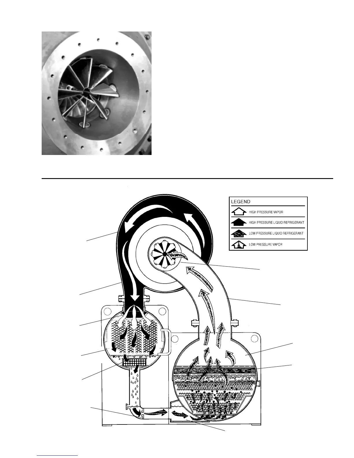
FIG. 2 – REFRIGERANT FLOW-THRU CHILLER
PREROTATION VANES
(See Detail A)
SUCTION
COOLER
ELIMINATOR
OIL COOLER
LD00924
FLOW CONTROL
ORIFICE
SUB-COOLER
CONDENSER
DISCHARGE
BAFFLE
DISCHARGE
COMPRESSOR

 Loading...