5
YORK INTERNATIONAL
FORM 201.19-EG4
LD05809
capacity.
• Automatic spring return of capacity control valve to
minimum load position ensures compressor starting
at minimum motor load. Internal discharge check to
prevent rotor backspin upon shut-down.
• Acoustically Tuned, internal discharge gas mufer
eliminates objectionable noise at the source, while
optimizing ow for maximum performance.
• Reliable suction gas cooled, high efciency, accessible
hermetic motor with APT2000 type magnet wire and
redundant overload protection using both thermistor
and current overload protection.
• Suction gas screen and serviceable, 0.5 micron full
ow oil lter within the compressor housing.
• Cast iron compressor housing precisely machined
for optimal clearances and superb efciency. Entire
compressor, from suction to discharge has a Design
Working Pressure of 450 PSIG (31 Bar).
• 350W compressor body cartridge heater.
REFRIGERANT CIRCUIT:
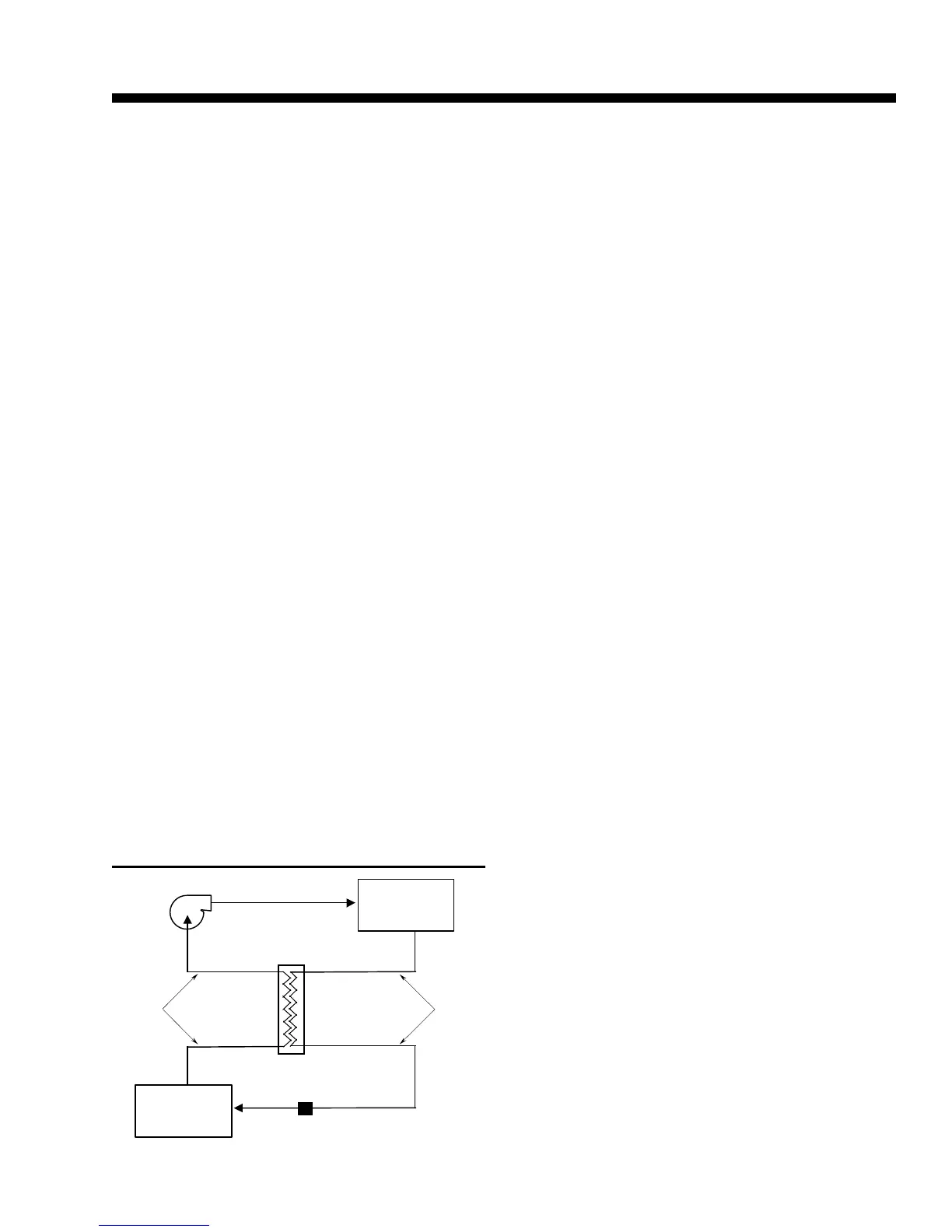
• Each refrigerant circuit of YORK’s eco
2
design utilizes
a Suction Line Heat Exchanger (SLHX), a refrigerant
to refrigerant, compact, shell and tube type heat ex-
changer to maximize chiller capacity and efciency by
subcooling liquid refrigerant delivered to the expansion
valve and superheating suction gas delivered to the
compressor. Design Working Pressure of 450 PSIG
(31 Bar) and either U.L./cU.L. listed or constructed
in accordance with applicable pressure vessel safety
Code (such as TÜV).
• Independent refrigerant circuits per compressor, each
using copper refrigerant pipe formed on computer con-
trolled bending machines. This eliminates over 60% of
system piping brazed joints as compared to designs
that use ttings, resulting in a highly reliable and leak
resistant system.
• Liquid line components include: manual shut-off valve
with charging port, high adsorption removable core
lter-drier, solenoid valve, sight glass with moisture-in-
dicator, and reliable thermostatic expansion valves.
• Discharge line provided with manual compressor shut-
off service valve (suction line shutoff valve optional).
Suction line equipped with closed-cell insulation.
• Oil separators with Design Working Pressure of 450
PSIG (31 Bar) and U.L. listing are high efciency,
augmented gas impingement type to maximize oil
extraction without fragile media to break down.
• Oil cooling provided by dedicated air cooled nned
tube type heat exchanger located in the condenser
section of the machine.
CONDENSER SECTION:
• Condenser Fans with low noise, full airfoil cross sec-
tion for maximum efciency, statically and dynamically
balanced vibration free operation, and positioned in
extended, formed steel orices for low sound and
maximum efciency.
• Condenser fan motors are high efciency, direct drive,
6-pole, 3-phase, Class-“F,” current overload protected,
totally enclosed (TEAO) type with double sealed, per-
manently lubricated ball bearings.
• Fin and tube condenser coils of seamless, internally
enhanced, high condensing coefcient, corrosion
resistant copper tubes arranged in staggered rows.
• Fins are mechanically bonded to corrosion resistant
aluminum alloy ns with full height n collars. Design
working pressure is 450 PSIG (31 Bar).
COMPLETE FACTORY PACKAGE:
• Each compressor is installed on its own independent
refrigerant circuit, which is factory pressure tested,
evacuated, then fully charged with refrigerant and
oil.
• After assembly, an operational test is performed with
water owing through the cooler to ensure each circuit
operates correctly.
• Cabinet and base frame are constructed of formed
heavy gauge, galvanized steel.
• All external structural parts are covered with archi-
tecturally neutral “Desert Sand” (Munsell #10YR6-2)
baked-on enamel powder paint. This provides a nish
which, when subjected to ASTM B117, 500 hour, 5%
salt spray conditions, shows breakdown of less than
1/8" either side of a scribed line (equivalent to ASTM
D1654 rating of “6”).
• Design is in accordance with applicable sec-
tions of ASME Pressure Vessel Code, NFPA
70 (National Electrical Code), U.L. and cU.L.
 Loading...