254595-YTG-C-0308
28 Johnson Controls Unitary Products
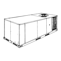
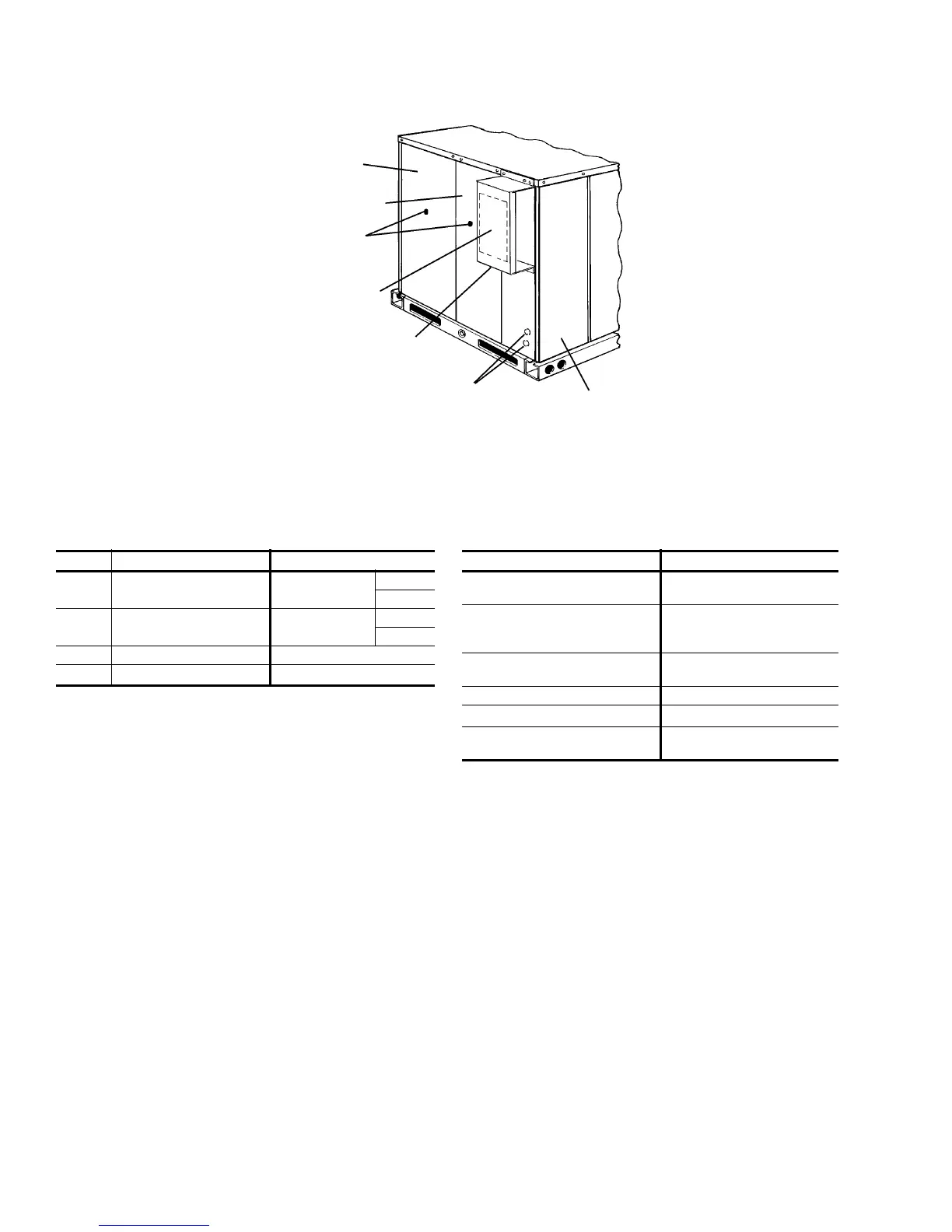
FIGURE 7 - DISCONNECT/BLOWER ACCESS LOCATION
Disconnect Switch Location
and Motor Access Panel for
Unit with “Belt-Drive” Option
Control Box Access
A,B
Wiring Entry
(See Detail “B”)
Mounting Bracket for
Disconnect Switch
(Field Supplied)
Field-Supplied Disconnect
Switch Location
Blower Motor Access
Filter Access
Dot Plugs
TABLE 28: UTILITIES ENTRY
HOLE OPENING SIZE (DIA.) USED FOR
A
7/8” KO
1
Control Wiring
2
Side
Bottom
B
2” KO
1
Power Wiring
Side
Bottom
C
1-5/8” KO Gas Piping (Front)
D
1-1/2” KO
Gas Piping (Bottom)
1. Opening in the bottom to the unit can be located by the
side in the insulation.
2. Do not remove the 2” knockout ring.
TABLE 29: MINIMUM CLEARANCES
LOCATION
CLEARANCE
Front
24” (Cooling/Electric Heat)
32” (Gas Heat)
Rear
12” (Less Economizer)
36” (With Economizer or Fixed
Air/Motorized Damper)
Left Side (Filter Access)
24” (Less Economizer)
36” (With Economizer)
Right Side (Cond. Coil)
24”
Below Unit
1
0”
Above Unit
2
72” (For
Condenser Air Discharge)
1. Units may be installed on combustible floors made
from wood or class A, B, or C roof covering material.
2. Units must be installed outdoors. Overhanging struc-
tures or shrubs should not obstruct condenser air dis-
charge outlet.
 Loading...