28
YORK INTERNATIONAL
FORM 201.19-NM8 (804)
Installation
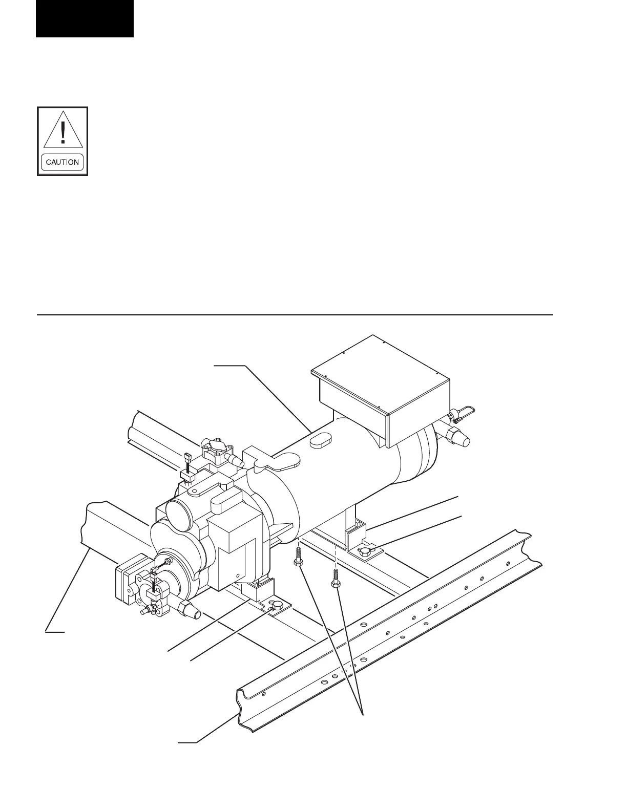
COMPRESSOR FEET BOLT REMOVAL
After the chiller is placed in the fi nal location, remove
the four bolts, 1 , attaching the compressor feet to the
frame rails. These bolts are only used for shipping
purposes. The bolts are screwed into the compressor
feet from the bottom side of the frame rail. Refer to
Figure 5.
After the four shipping bolts are removed from the
compressor feet, the compressor will be held in place
by the four corner brackets, 2.
This assembly reduces compressor noise by isolating
the compressor from the base rails.
DO NOT remove the four 3/8" bolts, 3, mounting the
corner brackets, 2, to the frame rails.
1
2
2
COMPRESSOR
CHANNEL BASE
BASE SUPPORT
RAIL
3
3
LD09131
FIG. 5 – COMPRESSOR MOUNTING
Where accumulation of snow is likely, ad di tion al height
must be provided under the unit to ensure normal air fl ow
to the unit.
The clearance dimensions given are
nec es sary to main tain good airfl ow
and en sure cor rect unit op er a tion. It
is also nec es sary to con sid er access
re quire ments for safe op er a tion and
maintenance of the unit and power
and control pan els. Lo cal health and
safe ty reg u la tions, or prac ti cal con-
sid er ations for ser vice re place ment
of large com po nents, may require
larg er clear anc es than those given
in the Tech ni cal Data Section of this
manual, (page 102).
 Loading...