JOHNSON CONTROLS
113
SECTION 6 – COMMISSIONING
FORM 150.72-ICOM6
ISSUE DATE: 08/03/2022
6
Switch Settings
Ensure the chiller OFF/ON UNIT switch at the bottom
of the keypad is OFF. Place the optional circuit breaker
handle on the panel door to ON. The customer’s dis-
connection devices can now be set to ON.
Verify the control panel display is illuminated. Ensure
the system switches under the SYSTEM SWITCHES
key are in the OFF position.
Supply Voltage
Verify that the site voltage supply corresponds to the
unit requirement and is within the limits given in SEC-
TION 5 – TECHNICAL DATA.
Water System
Verify the chilled liquid system has been installed cor-
rectly, and has been commissioned with the correct
direction of water flow through the cooler. The inlet
should be at the refrigerant piping connection end of
the cooler. Purge air from the top of the cooler using
the plugged air vent mounted on the extension pipe.
Flow rates and pressure drops must be within the limits
given in SECTION 5 – TECHNICAL DATA. Operation
outside of these limits is undesirable and could cause
damage.
If mains power must be switched OFF for extended
maintenance or an extended shutdown period, the com-
pressor suction, discharge and economizer service stop
valves should be closed (clockwise). If there is a pos-
sibility of liquid freezing due to low ambient tempera-
tures, the coolers should be drained or power should be
applied to the chiller. This will allow the cooler heater
to protect the cooler from freezing down to –20°F. Be-
fore placing the unit back in service, valves should be
opened and power must be switched ON (if power is
removed for more than 8 hours) for at least 8 hours (24
hours if ambient temperature is below 86°F [30°C])
before the unit is restarted.
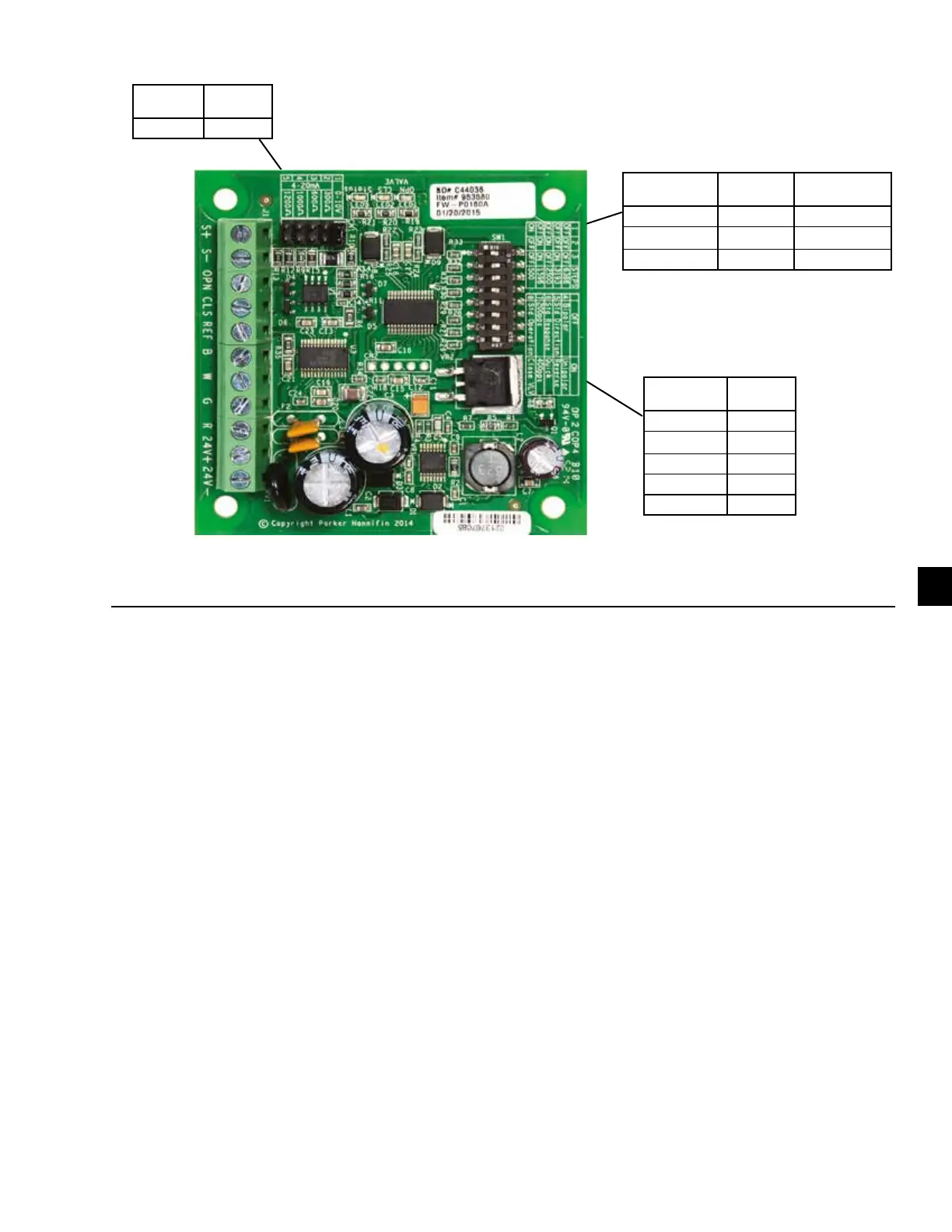
JUMP
LOCATION
INPUT
SIGNAL
1 0–10 V
FIGURE 36 - EEV IB-G INTERFACE BOARD
DIP SWITCH
NUMBER
ALL
CHILLERS
4 OFF
5 OFF
6 ON
7 OFF
8 OFF
DIP SWITCH
NUMBER
YLAA0230
ALL OTHER
CHILLERS
1 OFF OFF
2 OFF ON
3 OFF OFF
 Loading...