JOHNSON CONTROLS
42
FORM 150.72-ICOM6
ISSUE DATE: 08/03/2022
SECTION 4 – INSTALLATION
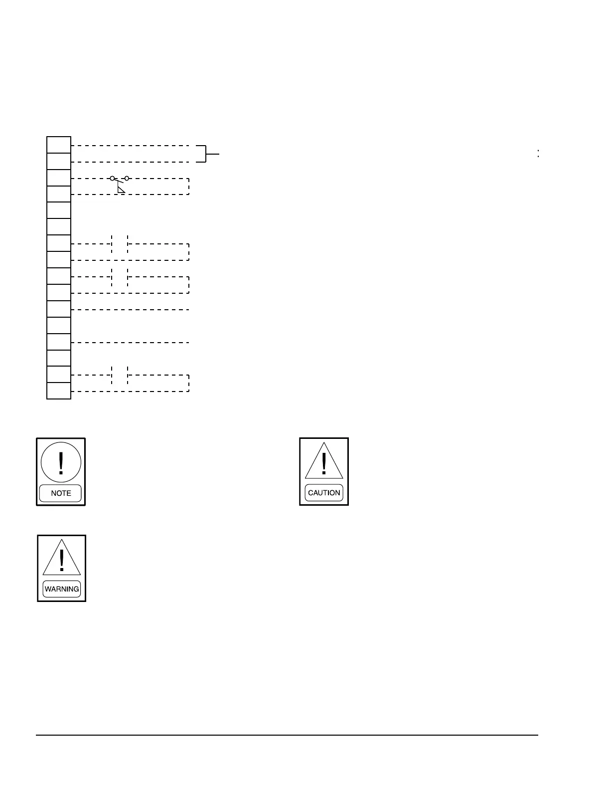
FIGURE 12 - CONTROL WIRING INPUTS
USER CONTROL WIRING INPUTS
LD13130
A-
A+
14
13
50
13
21
13
20
13
19
13
18
13
51
13
INTERNAL WIRING TO OPTIONAL REMOTE TEMP. RESET BOAR
FLOW SWITCH
REMOTE UNLOAD STEP 1
PWM REMOTE TEMP RESET
INTERNAL WIRING TO 2-KCR CONTROL RELAY
INTERNAL WIRING TO 1-KCR CONTROL RELAY
REMOTE START / STOP
INTERNAL WIRING TO OPTIONAL REMOTE TEMP. RESET BOARD
All externally supplied contacts must be
capable of switching 24 VDC / 115 VAC.
Gold contacts are recommended. If sup-
plied contacts are from a Relay / Contac-
tor (Inductive Load), the coil of the Relay
/ Contactor must be suppressed. Typical
suppressor is P/N 031-00808-000.
The unit evaporator heater uses 120 VAC.
Disconnecting 120 VAC power from the
unit, at or below freezing temperatures,
can result in damage to the evaporator
and unit as a result of the chilled liquid
freezing.
It is possible that multiple sources of
power can be supplying the unit power
panel. To prevent serious injury or death,
the technician should verify that NO
LETHAL VOLTAGES are present inside
the panel AFTER disconnecting power,
before working on equipment.
 Loading...