JOHNSON CONTROLS
14
Form 160.78-O1
Issue date: 05/19/2021
Section 2 - System operating procedures
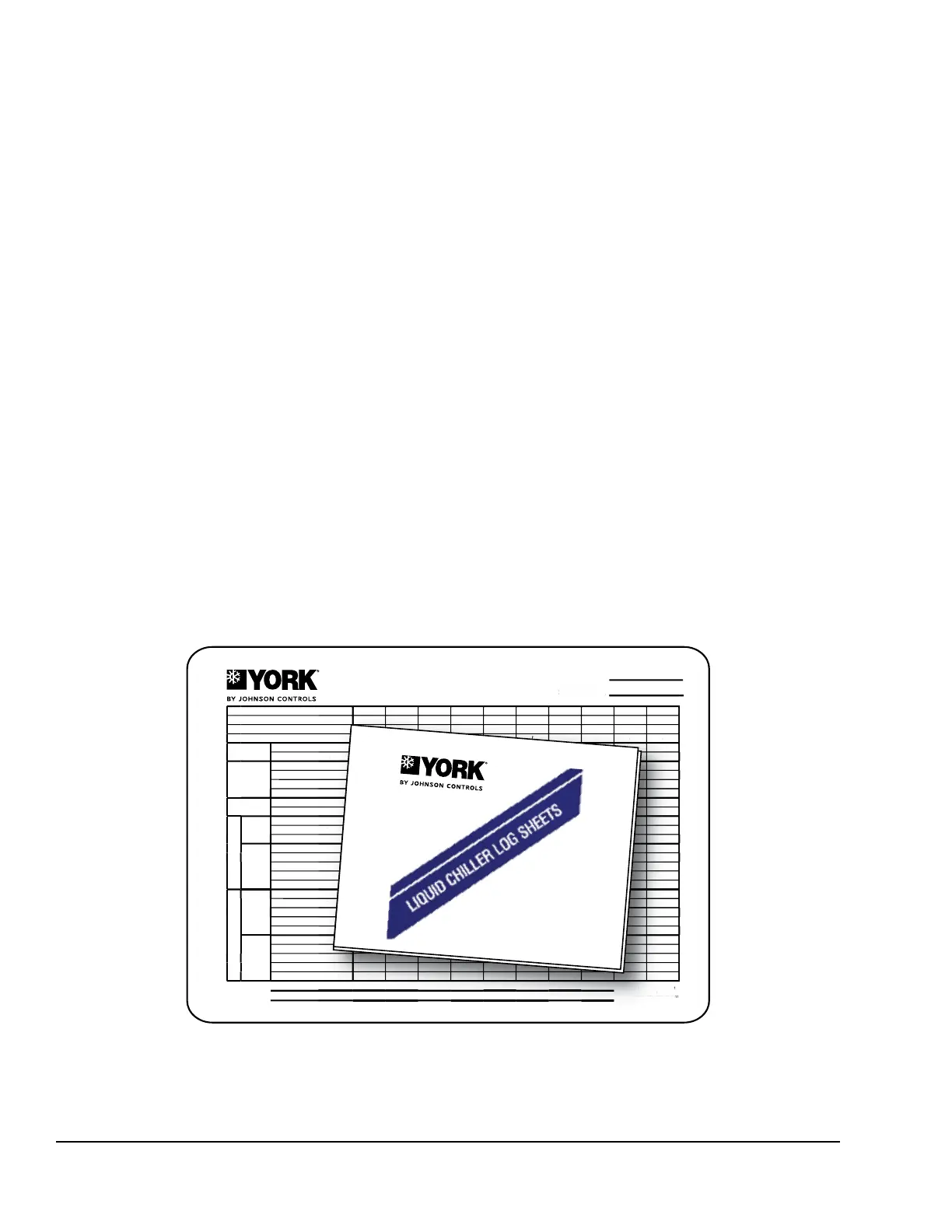
is available for this purpose. Figure 4 shows an ex-
ample log sheet used by Johnson Controls Personnel
for recording test data on chiller systems. Log sheets
are available in pads of 50 sheets and can be obtained
through the nearest Johnson Controls office. Request
the YMC
2
Centrifugal Liquid Chiller Log Sheets (Form
160.78-MR1).
An accurate record of readings serves as a valuable ref-
erence for operating the system. Readings taken when
a system is newly installed will establish normal condi-
tions with which to compare later readings.
For example, an increase in condenser approach tem-
perature (condenser temperature minus leaving con-
denser water temperature) may be an indication of
dirty condenser tubes.
Operating inspections
By following a regular inspection using the display
readings of the OptiView™ Control Center, and main-
tenance procedure, the operator will avoid serious op-
erating difficulty. The following list of inspections and
procedures should be used as a guide.
Daily
1. Check OptiView™ Control Center displays.
2. Check entering and leaving condenser water pres-
sure and temperatures for comparison with job
design conditions. Condenser water temperatures
can be checked on the SYSTEM Screen.
3. Check the entering and leaving chilled liquid tem-
peratures and evaporator pressure for compari-
son with job design conditions on the SYSTEM
Screen.
4. Check the condenser saturation temperature on
the SYSTEM Screen.. This temperature is based
on the condenser pressure that is detected by the
condenser transducer.
5. Check the compressor discharge temperature on
the SYSTEM Screen. During normal operation
discharge temperature should not exceed 220°F
(104°C).
6. Check the compressor motor current on the SYS-
TEM Screen.
Figure 4 - Liquid chiller log sheets
CENTRIFUGAL
LIQUID CHILLER LOG SHEET
Chiller Location
System No.
Date
Time
Hour Meter Reading
O.A. Temperature Dry Bulb / Wet Bulb / / / / / / / / / /
Compressor
Discharge Temperature
PRV % Open (If equipped)
Motor
Input Power
% Input FLA
% Motor FLA
DC Bus Voltage
Magnetic Bearing
Controller
Motor Housing Temperature
Rotor Elongation
Evaporator
Refrigerant
Suction Pressure
Corresponding Temperature
Small Temperature Difference
Liquid
Supply Temperature
Supply Pressure
Return Temperature
Return Pressure
Flow Rate - GPM (If equipped)
Condenser
Refrigerant
Discharge Pressure
Corresponding Temperature
Subcooler Liquid Temperature
Small Temperature Difference
Refrigerant Level
Liquid
Supply Temperature
Supply Pressure
Return Temperature
Return Pressure
Flow Rate - GPM (If equipped)
Remarks:
Form 160.78-MR1 (611)
New Release
Issue Date: June 30, 2011
...an Energy-Saving
approach to your
Service needs...
Issue Date:
June 30, 2011
Form 160.78-MR1 (611)
New Release
YMC
2
CENTRIFUGAL
LD16236
* NOTE: A pad of 50 log sheets can be ordered from your local Johnson Controls branch by
requesting Form 160.78-MR1.

 Loading...