JOHNSON CONTROLS
20
Form 160.78-O1
Issue date: 05/19/2021
Section 3 - Maintenance
When this point is reached, practically all of the air
has been evacuated from the system, but there is still
a small amount of moisture left. In order to provide
a medium for carrying this residual moisture to the
vacuum pump, nitrogen must be introduced into the
system to bring it to atmospheric pressure and the indi-
cator temperature will return to approximately ambient
temperature. Close off the system again, and start the
second evacuation.
The relatively small amount of moisture left will be
carried out through the vacuum pump and the tem-
perature or pressure shown by the indicator should
drop uniformly until it reaches a temperature of 35°F
(1.6°C) or a pressure of 5 mm Hg.
When the vacuum indicator registers this tempera-
ture or pressure, it is a positive sign that the system
is evacuated and dehydrated to the required limit. If
this level cannot be reached, it is evident that there is a
leak somewhere in the system. Any leaks must be cor-
rected before the indicator can be pulled down to 35°F
(1.6°C) or 5 mm Hg in the primary evacuation.
During the primary pulldown, makes sure that the wet
bulb indicator temperature does not fall below 35°F
(1.6°C). If the temperature is allowed to fall to 32°F
(0°C), the water in the test tube will freeze, and the
result will be a faulty temperature reading.
Refrigerant charging
To avoid the possibility of freezing liquid within the
evaporator tubes when charging an evacuated system,
only refrigerant vapor from the top of the drum or cyl-
inder must be admitted to the system pressure until the
system pressure is raised above the point correspond-
ing to the freezing point of the evaporator liquid. For
water, the pressure corresponding to the freezing point
is 29 psig (200 kPa) for R-134a (at sea level).
While charging, every precaution must be taken to pre-
vent moisture laden air from entering the system. Make
up a suitable charging connection from new copper
tubing to fit between the system charging valve and the
fitting on the charging drum. This connection should
be as short as possible but long enough to permit suf-
ficient flexibility for changing drums. The charging
connection should be purged each time a full container
of refrigerant is connected and changing containers
should be done as quickly as possible to minimize the
loss of refrigerant.
Refrigerant is furnished in cylinders that contain ei-
ther 30 lb, 50 lb, 125 lb, 1,025 lb, or 1750 lb. (13.6 kg,
22.6 kg, 56.6 kg, 464 kg, or 794 kg) of refrigerant.
Checking the refrigerant charge during
unit shutdown
The refrigerant charge is specified for each chiller
model in Table 2. Charge the correct amount of refrig-
erant and record the level in the evaporator sight glass.
The refrigerant charge should always be checked and
trimmed when the system is shut down.
Charge the refrigerant in accordance with the method
shown in Refrigerant charging in this section. The
weight of the refrigerant charged should be recorded
after initial charging.
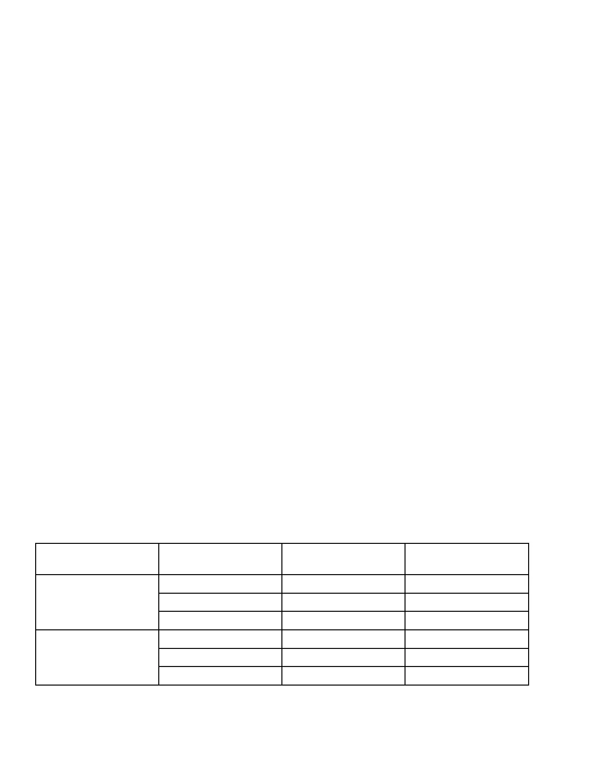
Table 2 - Refrigerant charge
Compressor Evaporator Condenser
Estimated refrigerant
charge, lb (kg)
1
M1-197FAA
EA2510 CA2110 570 (260)
EA2510 CA2510 625 (285)
EA2514 CA2514 860 (390)
M2-205FAA
EA2510 CA2110 555 (255)
EA2510 CA2510 610 (280)
EA2514 CA2514 860 (390)
1 Refrigerant charge quantity and weights will vary based on tube count.
Refer to product drawings for detailed weight information.

 Loading...