FORM NO.: 6U5M-A11M-NB-EN
JOHNSON CONTROLS 27
ELECTRICAL DIAGRAM
All electrical wiring should be carried out in accordance with local regulations. Route properly sized cables to the
cable entries in the side of the unit.
It is the responsibility of the user to install over current protection devices between the supply conductors and the
power supply terminals on the unit.
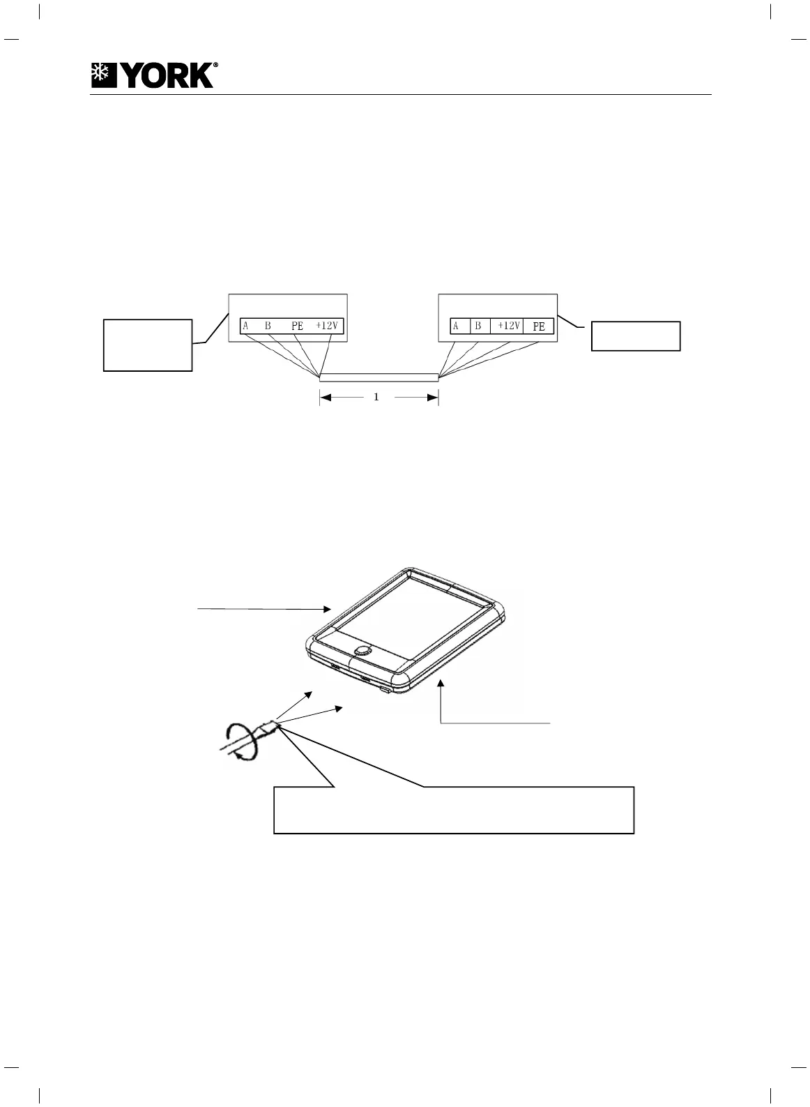
Wire Controller Installation
STEP 1: Wiring
FIGURE 24 – WIRE CONTROLLER CONNECT TO UNIT
Notes
:
1. Total length of communication and power supply line should be within 15m.
2. A, B, 12V, and 0V should be connected correspondingly in case of malfunction or controller damage.
STEP 2: Panel Disassembly
FIGURE 25 – WIRE CONTROLLER STRUCTURE
Notes: As printed circuit board is on the front panel of controller, be cautious when using flat-head screwdriver.
1# Modular
Wire
Controller
Front panel of controller
Back panel of controller
Insert and turn flat-head screwdriver slightly and separate the front and
back panels.
Cooke Industries - Phone: +64 9 579 2185 Email: sales@cookeindustries.co.nz Web: www.cookeindustries.co.nz
 Loading...