Page - 14/85 AF2ZP0CL - ACE2 - User Manual
The black lines are the power cables.
This is apparently a good layout, but can bring to errors in the can line.
The best solution depends on the type of nodes (modules) connected in the
network.
If the modules are very different in terms of power, then the preferable
connection is the daisy chain.
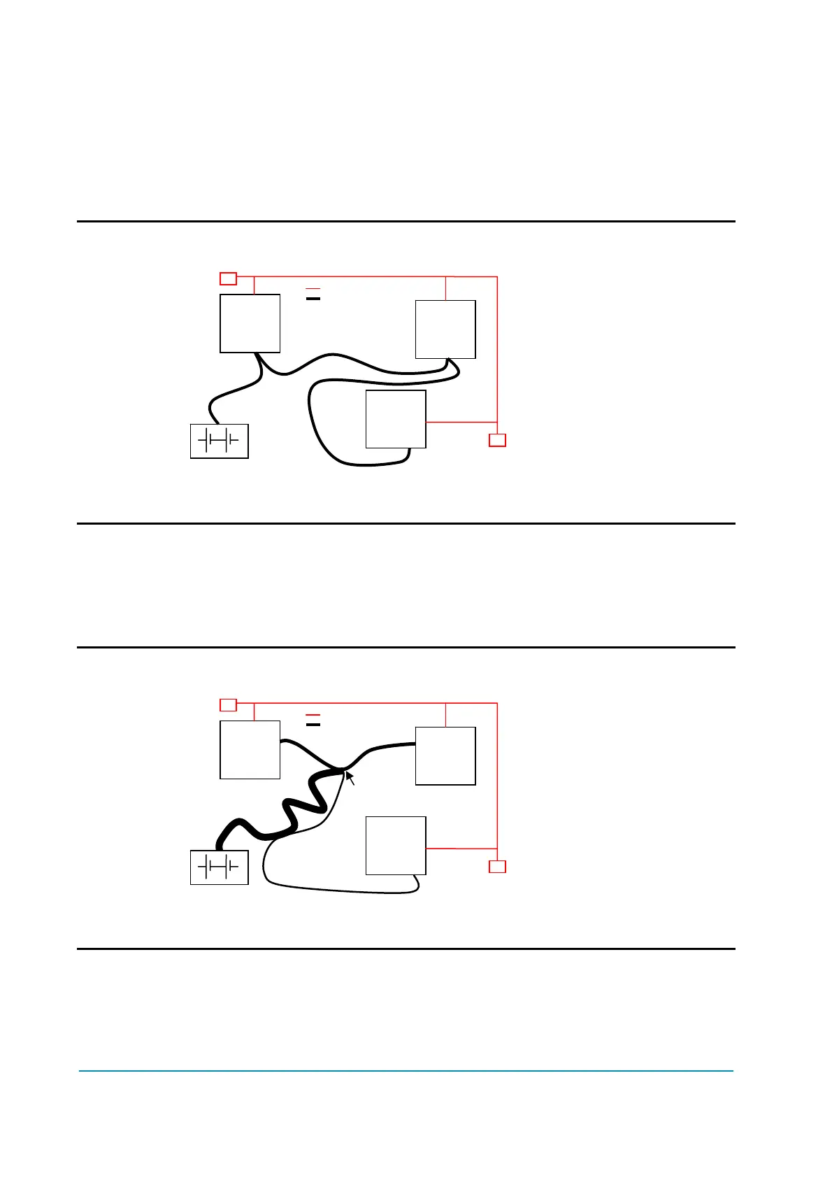
U Correct Layout:
Note: Module 1 power > Module 2 power > Module 3 power
The chain starts from the –BATT post of the controller that works with the
highest current, and the others are connected in a decreasing order of power.
Otherwise, if two controllers are similar in power (for example a traction and a
pump motor controller) and a third module works with less current, the best way
to deal this configuration is to create a common ground point (star configuration).
U Correct Layout:
Note: Module 1 power ≈ Module 2 power > Module 3 power
In this case the power cables starting from the two similar controllers must be as
short as possible. Of course also the diameter of the cable concurs in the voltage
drops described before (higher diameter means lower impedance), so in this last
example the cable between the minus of the Battery and the common ground
point (pointed by the arrow in the image) must be dimensioned taking into
Module
1
Module
2
Module
3
R
R
Can Bus
Center of the Ground connection
Module
1
Module
2
Module
3
R
R
Can Bus
 Loading...