Page 21
8 DESCRIPTION OF CONNECTORS
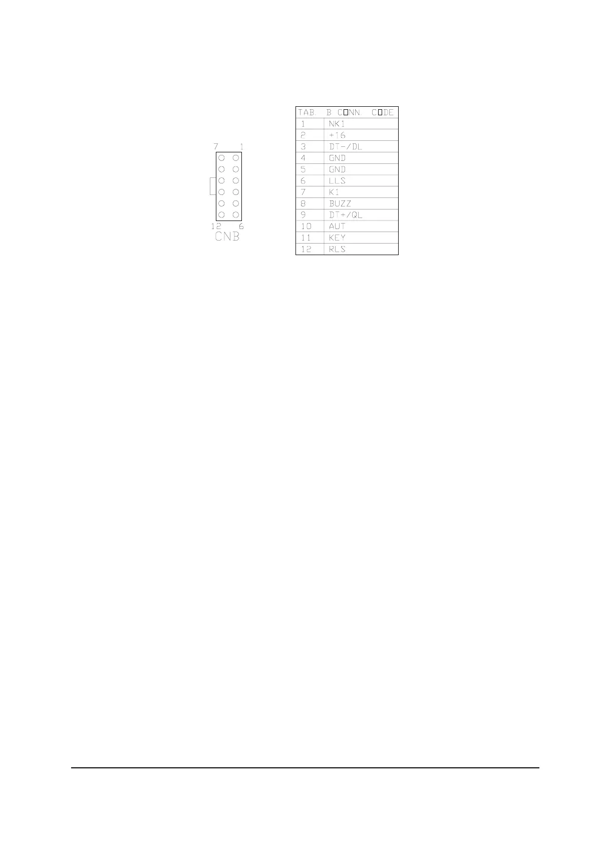
8.1 CNB CONNECTOR
1 NK1 This is the second (lower potential) safety switch connection.The first
connection is on Pin #7. If jumper J2 is closed, the Pin # 1 is ground
referenced and NK1 is at ground (GND) potential. If jumper J2 is
open, NK1 is floating. (It assumes an externally applied potential).
NK1 must be connected to an equal or lower potential than K1 (Pin
#7 of CNB).
2 +16 Output for internally provided +16Vdc stabilized supply. It may be
used for the status device supply. The maximum rated output is
40mAmps. Warning: do not short circuit this pin because it is
common with the Electric Power Steering card supply.
3 DT-/DL For the tacho-generator application this is a tacho-generator
connection. It is internally connected to battery negative (GND). For
the stepper motor application this is a stepper motor line (called D
line).
4 GND This is internally connected to ground (battery minus) reference. It
may be used for the GND reference of the Automatic Centering
request switch and for the stepper motor GND connection.
5 GND This is internally connected to ground (battery minus) reference. It
may be used for the GND reference of the limit switches.
6 LLS Left (CCW) Limit Switch. It's possible to stop steering in the direction
that causes negative signal from the tacho-generator by closing the
connection between LLS (Pin #6) and negative (GND Pin#5).
Therefore, connection of a normally open switch between Pin #6 and
Pin #5 acts as a Counter-Clockwise steering limit switch.

 Loading...