Do you have a question about the Zapi EPS-AC0 and is the answer not in the manual?
| Brand | Zapi |
|---|---|
| Model | EPS-AC0 |
| Category | Controller |
| Language | English |
Details controller features like motor type, interfaces, and environmental specs.
Visual representation of the eps-ac0 controller's internal components and connections.
Lists voltage, current, and power supply requirements for the controller.
Provides physical dimensions and connector details of the eps-ac0 unit.
Explains how the eps-ac0 controls steering using stepper motor or twin pot.
Describes the function to align the steered wheel straight ahead in an aisle.
Lists key operational capabilities like sensitivity adjustments and CAN bus integration.
Details how the system provides diagnostic information and failure codes.
Describes the AC induction motor used for steering and its power rating.
Specifies recommended gear ratios for steering wheel and motor shaft.
Details the controller's PCB, microprocessors, and memory capabilities.
Illustrates the printed circuit board layout of the eps-ac0 controller.
Explains configurations for steering sensors: stepper motor or twin pot.
Details part numbers and mechanical dimensions for suitable stepper motors.
Describes the double potentiometer used for steering angle feedback.
Covers mandatory and suggested sensors for closing the steering loop.
Details one arrangement for feedback sensors: encoder and potentiometer.
Explains the role of the feedback potentiometer for initialization and redundancy.
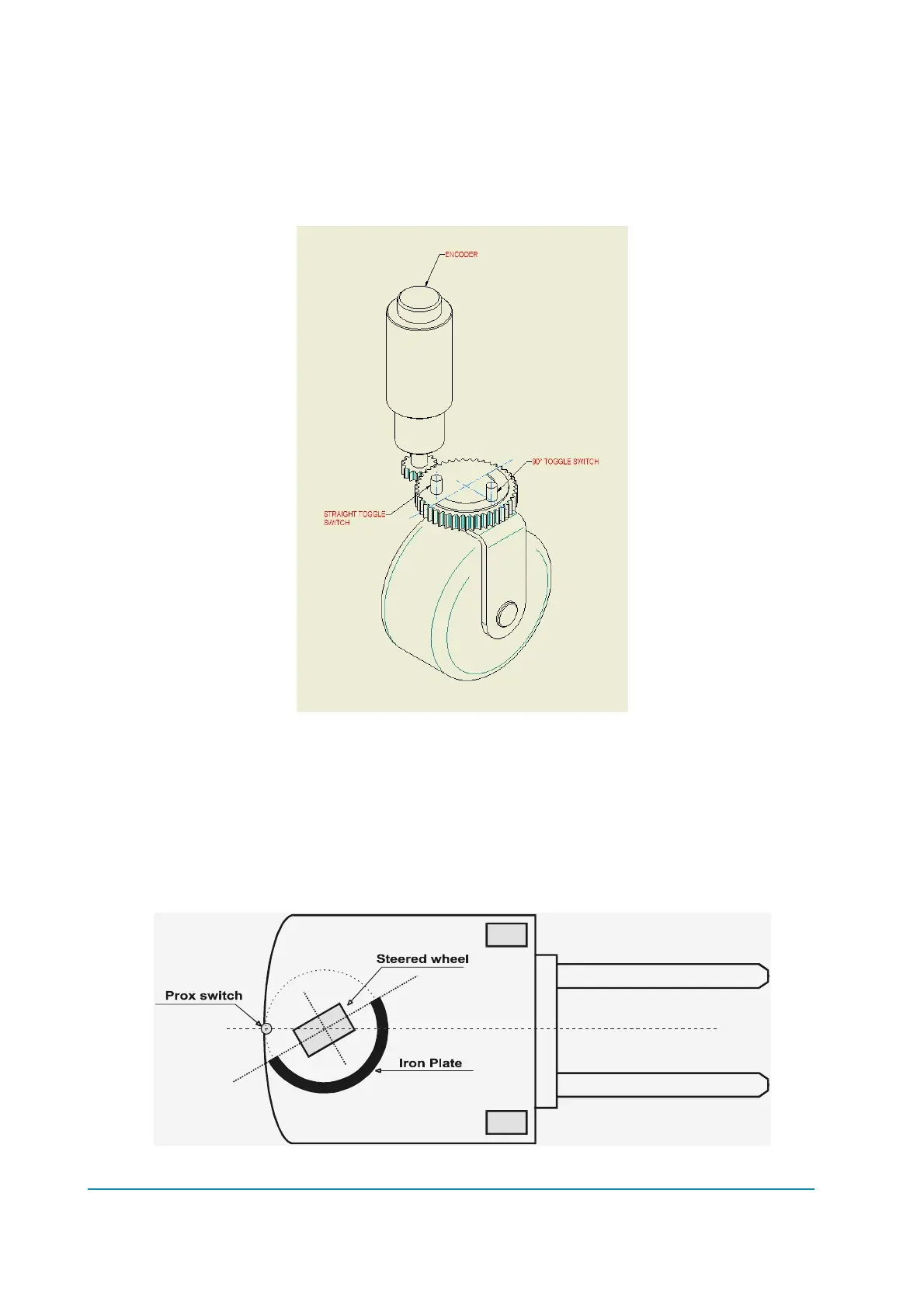
Describes feedback using an encoder and toggle switches for straight-ahead detection.
Details the NPN type straight-ahead toggle switch and its connection.
Highlights the advantage of using low-resolution encoders for angle measurement.
Shows how to connect the AC motor phases and battery to the controller.
Wiring diagram for the EPS-AC0 controller with a stepper motor setup.
Wiring diagram for the EPS-AC0 controller with a twin pot setup.
Provides recommendations for connecting the stepper motor to the controller.
Offers suggestions for connecting the twin pot as an alternative to the stepper motor.
Describes the use and connection of three digital inputs for various functions.
Explains the internal safety contact and its connection for stopping traction/brakes.
Discusses heat dissipation requirements and methods for the controller.
Provides guidance on installing the controller using a flat metallic surface for heat dissipation.
Offers advice on using a finned heatsink and fans for cooling when base plate installation is not feasible.
Offers critical recommendations for safe and proper installation of the inverter.
Specifies cable types, sections, and length recommendations for power and auxiliary circuits.
Recommends fuse ratings for auxiliary circuits and the power stage.
Discusses the usefulness of a power contactor for battery disconnection during power failures.
Explains CAN bus communication, cable requirements, and termination resistance.
Provides checks for crimped cables and connector insertion for I/O connections.
Details the controller's compliance with safety norms and the manufacturer's responsibility.
Discusses Electromagnetic Compatibility (EMC) and its influence on system performance.
Explains electromagnetic emission and methods to reduce it via shielding and layout.
Provides suggestions to improve the controller's immunity to external electromagnetic fields.
Addresses Electrostatic Discharge (ESD) risks and prevention methods for the controller.
Explains dither in closed-loop applications and countermeasures.
Details the logic connectors (CNB, CNA) and their pin assignments.
Lists pin functions for the CNA connector, including inputs, CAN, and GND.
Lists pin functions for the CNB connector, including feedback, thermal sensor, and supply.
Details pin functions for the CNC connector, used for serial communication and console.
Shows the power connection terminals for battery and motor phases.
Step-by-step guide for installing a twin pot with encoder and feedback pot.
Procedure for installing twin pot, encoder, and straight-ahead switch for redundancy.
Procedure for installing a stepper motor with encoder and feedback pot.
Procedure for installing a stepper motor with encoder and toggle switches.
General procedure for setting up the controller based on truck configuration.
Setup steps for a system using only a stepper motor for steering.
Setup steps for systems requiring a stepper motor and automatic centering (AUTC).
Setup steps for systems using only a twin pot for steering.
Setup steps for systems requiring a twin pot and automatic centering (AUTC).
Provides a simplified setup procedure for trucks with default configurations.
Quick setup for open-loop manual mode with a stepper motor.
Quick setup for stepper motor systems with automatic centering.
Quick setup for twin pot systems with or without automatic centering.
Explains that parameter adjustments are made using the digital console.
Details the digital console's appearance, buttons, and connection to the inverter.
Describes the Zapi hand set functions and menu navigation structure.
Menu structure for setting up a stepper motor with encoder and feedback pot.
Guide to navigating the SET OPTIONS menu for controller configuration.
Guide to navigating the ADJUSTMENTS menu for parameter tuning.
Guide to navigating the SET MODEL menu for system configuration.
Selects steer configuration: open/closed loop, command sensor type.
Guide to navigating the PARAMETER CHANGE menu for adjusting settings.
Guide to hidden HARDWARE SETTINGS menu (requires Zapi technician).
Guide to hidden SPECIAL ADJUSTMENT menu (requires Zapi technician).
Provides real-time measurements for controller state and variables.
Procedure to self-acquire motor resistance for optimal performance.
Explains automatic alignment at rest position for open-loop applications.
Describes reducing steering sensitivity near the straight-ahead direction.
Provides special adjustment (DEBUG OUTPUT) for troubleshooting.
Lists alarms recorded in the controller's logbook with FIFO structure.
Details alarms indicated by a single blink, including MICRO SLAVE KO and errors.
Alarm for mismatching encoder counts between main and slave uC.
Alarm related to safety contact voltage on CNA#4 before closure.
Alarm for communication failure between main and slave uC via serial interface.
Alarm for communication failure between slave and main uC via serial interface.
Watchdog alarm when slave uC detects no SYNC signal from main uC.
Alarm if slave uC detects main uC safety contact closed before command.
Alarm if slave uC detects main uC safety contact open when expected closed.
Alarm if main uC detects slave uC safety contact closed before command.
Alarm if main uC detects slave uC safety contact open when expected closed.
Alarm if slave uC detects analog signal for reset outside expected window.
Details alarms indicated by two blinks, including HIGH CURRENT and POWER FAILURES.
Alarm if current limiting circuit is always active or repeatedly active.
Alarm for zero current in phase W when motor is commanded.
Alarm for zero current in phase U when motor is commanded.
Alarm for zero current in phase V when motor is commanded.
Alarm if real voltage between phases W and U differs from desired.
Alarm if real voltage between phases W and V differs from desired.
Alarm if traction controller fails to close main contactor via CAN.
Alarm if eps-ac0 fails to receive event messages from traction controller.
Alarm if steering motor current is high for over 1 sec.
Details alarms indicated by three blinks, including SENSOR KO and OUT OF RANGE.
Alarm for non-null mean voltage on stepper motor direct line (CNA#9).
Alarm for non-null mean voltage on stepper motor quadrature line (CNA#8).
Alarm for fault on command potentiometer (CPOC1/CPOC2).
Alarm for fault on feedback potentiometer (CPOT).
Alarm for error in redundant feedback sensor test (pot/encoder mismatch).
Alarm if command potentiometer jerks larger than MAX SP SLOPE.
Alarm if feedback potentiometer jerks larger than 0.3 V in 16 msec.
Alarm if feedback sensor value does not change when commanded.
Details alarms indicated by four blinks, including EEPROM KO and GAIN EEPROM KO.
Alarm if EEPROM write/read test fails or redundant locations mismatch.
Alarm if current amplifier gain parameters in EEPROM are inconsistent.
Alarm if current amplifier parameters are at default values.
Details alarms indicated by five blinks, including HIGH TEMPERATURE and MOTOR TEMPERAT.
Alarm if controller base plate temperature exceeds 75 degrees.
Alarm if motor temperature exceeds 150 degrees.
Details alarms indicated by six blinks, including STBY I HIGH and LOGIC FAILURES.
Alarm if current amplifier outputs are out of window or drift.
Alarm if motor voltage amplifier outputs are not in the expected window.
Alarm if Vu-Vw voltage amplifier output drifts beyond tolerance.
Alarm if Vw-Vv voltage amplifier output drifts beyond tolerance.
Details alarms indicated by thirty-two blinks, including DATA ACQUISITION.
Alarm during motor resistance acquisition or gain parameter adjustment.
Warnings that reduce truck speed but do not cut off operation.
Warning that steering controller is limiting angle; no speed reduction.
Warning if eps-ac0 requests parameters from traction controller via CAN.
Warning if eps-ac0 awaits assent from traction controller to close safety contacts.
Alarm cutting off traction if straight-ahead condition is not met within 6 sec.
List of CAN Bus alarm codes supplied by the eps-ac0.
Procedures to test the controller's fault detection circuitry.