Page 5
The Procedure for automatic potentiometer signal acquisition is carried out using the
Console. This enables adjustment of the minimum and maximum useful signal level
(PROGRAM VACC function), in either direction. This function is unique when it is neces-
sary to compensate for asymmetry with the mechanical elements associated with the
potentiometer, especially relating to the minimum level.
The sequence of procedure is described in the programming console manual.
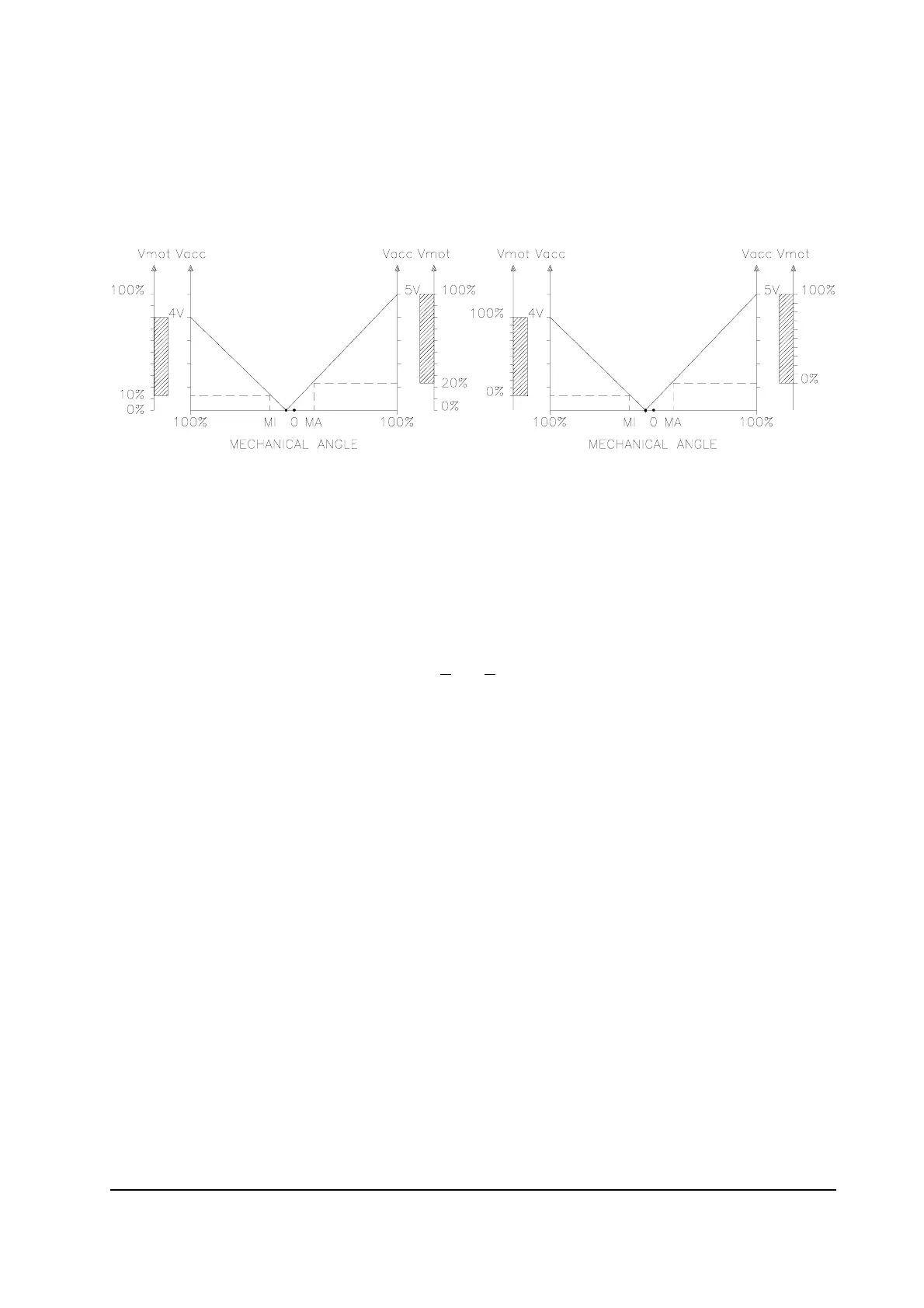
The two graphs show the output voltage from a non-calibrated potentiometer with
respect to the mechanical “zero” of the control lever. MI and MA indicate the point where
the direction switches close. 0 represents the mechanical zero of the rotation.
The Left Hand graph shows the relationship of the motor voltage without signal acquisition
being made. The Right Hand Graph shows the same relationship after signal acquisition
of the potentiometer.
2.4.c Other analog control unit
1) Input A13 (Saab connector version), A8 (Molex Minifit version) is an analog input,
whose typical application is for proportional braking. It should be in a 3 wire configura-
tion. Potentiometer value should be in the 0.5-10KW range. Generally, the load should
be in the 1.5mA to 30 mA range.
The CPOTB (A13, A8) signal range is from 0 to 10V.
2) Connections A3 (Saab), B6 (Minifit) (PTHERM) and A4 (Saab), B12 (minifit)
(NTHERM) are used for a motor thermal sensor. It can be digital (on/off sensor, nor-
mally closed) or analog. See also chapter 4.4 for more explanation.
2.4.d Speed feedback
The motor control is based upon the motor speed feedback. The speed transducer is an
incremental encoder, with two phases shifted at 90°. The encoder can be of different types
:
- power supply: +5V or +12V
- electric output: open collector ( NPN or PNP), push-pull, line driver
- standard (A and B) or differential (A, A, B, B) output
For more details about encoder installation see also chapter 3.6.
 Loading...