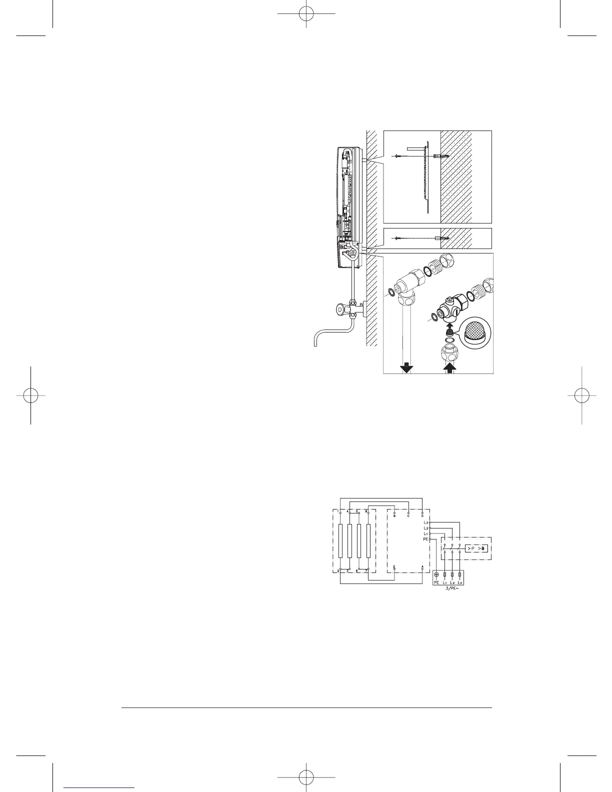
Wiring Diagram
1. Circuit board
2. Heating element
3. Safety thermal cut-out
4. Terminal block
Fig 6
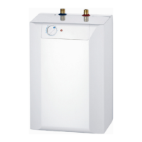
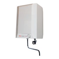
Surface mounted installation
1.For surface mounting, the two ½”
screw-in nipples and the ½” seals
must be screwed into the ½” union
nuts of the hot water and cold water
connectors.The two ½” caps of the
side outlets of the hot water and cold
water connectors must be removed
and screwed into the open end of the
screw-in nipples. The hot water and
cold water connectors must then be
screwed into the
3
/8” union nut of the
appliance and delivery pipe, together
with the
3
/8” seals.
2.When surface mounting, it is advisable
to install the appliance at a distance
from the wall as illustrated in Fig 6
using the spacer sleeves supplied. In
this case the two fixing holes near the
lower pipe connections should also
be used.
3.The flared end of the pipes must be
screwed into the ½” side outlets of the
hot water and cold water connectors
with ½” union nuts and ½” seals. The
holes required for the pipes must then
be broken out of the housing using a
blunt implement.
4.Ensure the line strainer is inserted into
the cold water connection.
Electrical connection
Prior to commencing electrical connection
take time to re-read the ‘Installation
Requirements’ listed on page 6 and
ensure that all requirements pertaining to
electrical installation are observed.
 Loading...