HydroTap Installation and Operating Instructions - 89650UK - August 2011 v1.02 Page 7 of 24
2. Cut a 50mm hole in the bench / sink top.
3. Ensure the silicon O-Ring remains in place as this is the moisture seal against the
bench / sink top. A light smearing of silicon sealant on the O-Ring will ensure a
watertight fit.
4. Pass all hoses through the 50mm hole and carefully locate the Head Assembly on the
bench / sink top.
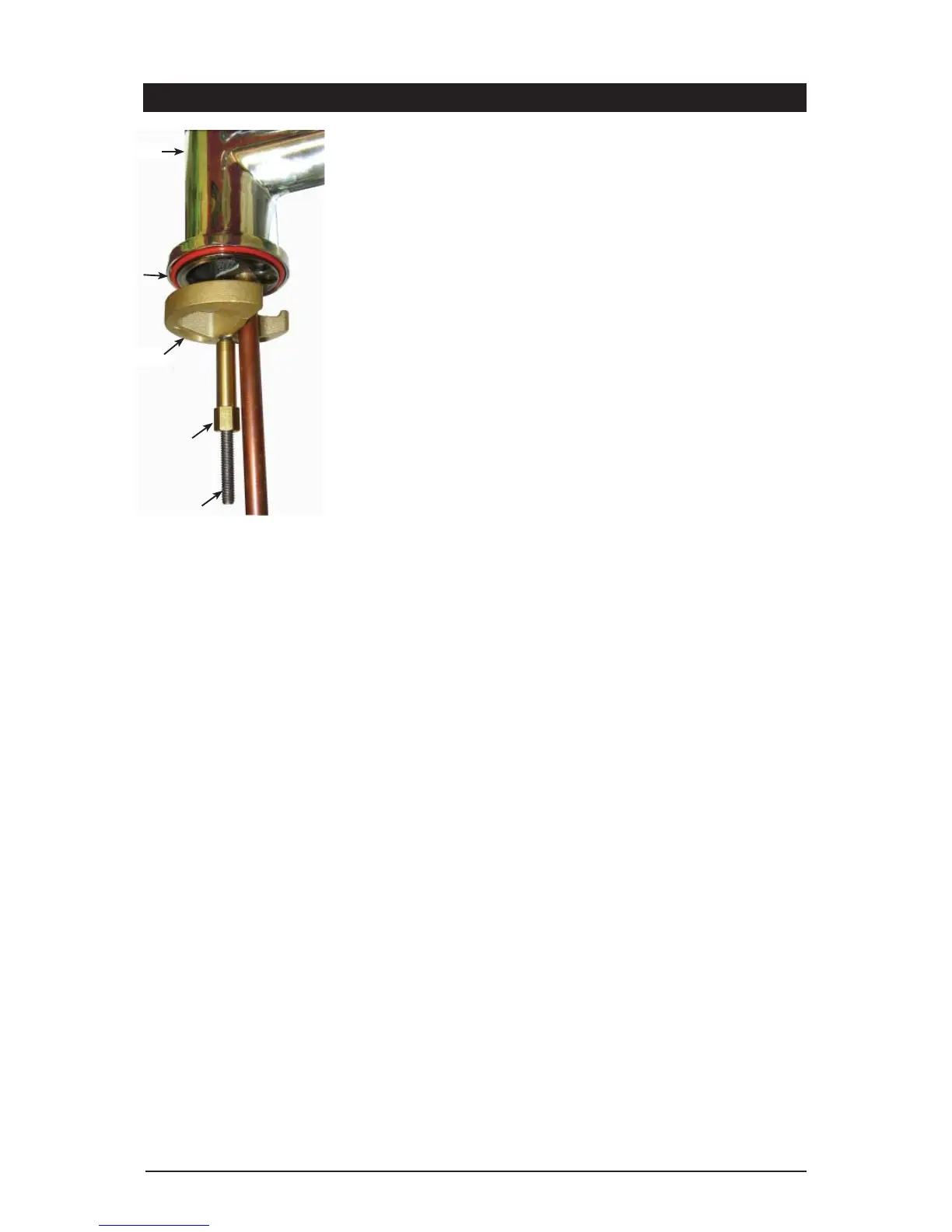
5. From the underside of the bench / sink, mount the ‘base block’ by feeding each of
the tubes and electrical cable evenly in between the legs of the ‘base block’. Slide it
up to meet the ‘all thread rod’, and pass the ‘all thread rod’ through the centre of the
‘base block’.
6. Hold the ‘all thread’ steady and fit the 10mm ‘fixing nut’ to the ‘all thread’ using
the tube spanner supplied in the kit. Check the Tap Head position before securing it
tightly against the bench / sink top.
NOTE 2: Under no circumstances should the Tap be twisted after the
installation is complete.
Step B - Installing the undersink unit
SPECIAL NOTE: The HydroTap undersink units are heavy, take note of the weights
listed in the table on page 6. If you think you cannot lift the unit safely, get help
and avoid possible injury.
Before positioning the heater connect the braided water inlet hose (supplied) to the cold
water tee piece (see Pages 12-15). Flush the hose prior to connecting to the cold water
inlet at the rear of the unit.
Position the HydroTap undersink unit as close as possible to directly beneath the All-in-
One tap head.
The connection tubes supplied with the tap head assembly CANNOT be lengthened.
Leave at least a 50 mm air-gap without obstruction on each side of the unit and 65mm
at the rear
Step C - Connecting the All-in-One tap outlet
Note:
Included in the installation pack are adhesive backed silicon buffers. If air vents are not
installed in the cupboards housing the HydroTap, the buffers must be placed on the
inside edge of the cupboard door to create a slight gap ensuring a minimum airflow.
Failure to do this may cause the HydroTap to overheat and operate inefficiently.
Model: Vented
Connect the 3 braided hoses to the rear of the undersink unit as shown in pages 14 -15.
Measure and trim the blue silicon tube and connect it to the chilled water outlet located
on the top front, right hand side of the undersink unit. Use spring clamps provided to
secure the hose.
Measure and trim the red silicon tube and connect it to the boiling water outlet located
on the top centre, right hand side of the undersink unit. Use spring clamps provided to
secure the hose.
Measure and trim the clear silicon tube and connect it to the vent outlet located on the
top centre, left hand side the top of the undersink unit. Use spring clamps provided to
secure the hose.
Installation Procedure (continued)
O - Ring seal
Base Block
Fixing nut
Tap
All-thread rod
NOTE :
New hose sets supplied with the
unit should be used. Do not use
old hose sets.
 Loading...