Chapter 3 – ACS 502 Installation Instructions
ACS 502 Installation & Start-up Manual 3-3
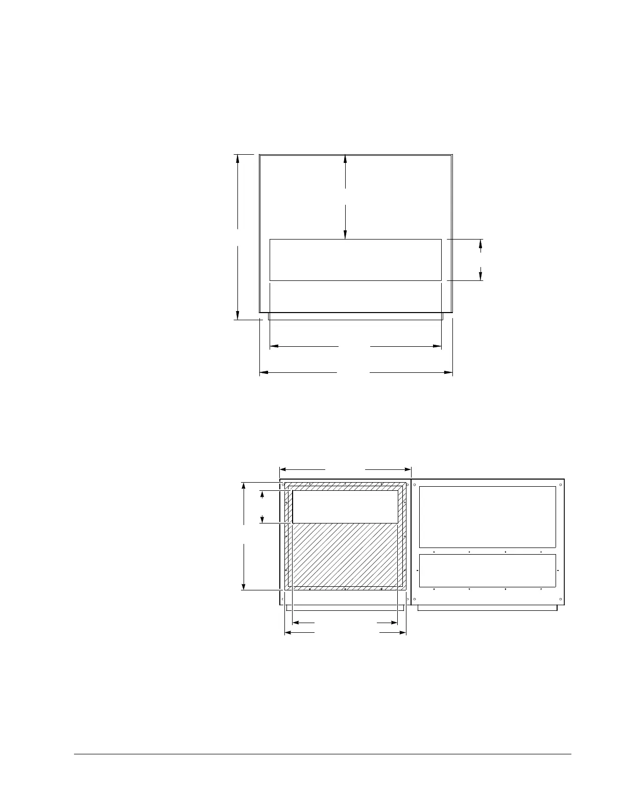
Conduit Size
Figure 3-2 and Figure 3-3 show top views of the ACS 502 and conduit entry
area. The panels must be removed from the drive before being drilled and
punched to prevent metal particles from falling into the drive.
Figure 3-2 ACS 502 Conduit Entry Area for One Door Enclosure
Figure 3-3 ACS 502 Conduit Entry Area for Two Door Enclosure
Figure 3-3 shows the left bay at the enclosure only.
TOP VIEW
5.906 in.
(150.0 mm)
27.559 in.
(700.0 mm)
23.622 in.
(600.0 mm)
24.516 in.
(622.7 mm)
12.113 in.
(307.7 mm)
Recommended area
for entry/exit
150.00 mm
[5.906"]
600.00 mm
[23.622"]
480.04 mm [18.899"]
491.55 mm
[19.352"]
553.25 mm [21.781"]
a300.dxf
 Loading...


