8 Advance Optima Ex Analyzer Modules Operator’s Manual 42/24-12-2 EN
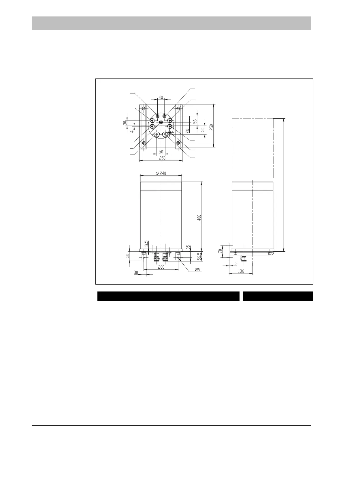
Dimensional Drawing
F
Note the additional space requirements
• Beneath the analyzer module for connection lines (approx. 10 cm) and
• Above the analyzer module for opening the housing (approx. 40 cm).
Figure 1
Ex Analyzer Module
(dimensions in mm)
5
3
4
8
6
1
2
7
9
10
800 (clearance for opening)
Caldos 15-Ex, Caldos 17-Ex, Magnos 106-Ex
Gas Connections:
1 Sample Gas Inlet
2 Sample Gas Outlet
3 Vent Opening
2)
4 Vent Opening
2)
5 Purge Gas Inlet
1)
6 Purge Gas Outlet
1)
Pressure Sensor (Caldos 17-Ex and Magnos 106-Ex
1)
Electrical Connections:
8 System Bus
9 24 VDC
10 Potential Compensation
1) Option
2) Version for sample gas under positive pressure only
Uras 14-Ex
Gas Connections:
1 )
2 ) See Analyzer
3 ) Data Sheet
4 )
5 Purge Gas Inlet
1)
6 Purge Gas Outlet
1)
7 Pressure Sensor
Electrical Connections:
8 System Bus
9 24 VDC
1
Potential Compensation
1) Option
 Loading...


