10 AWT420 | UNIVERSAL 4-WIRE, DUAL-INPUT TRANSMITTER | INF/ANAINST/012-EN REV. A
…4 Hazardous area considerations
Power supply connection
WARNING
Bodily injury.
USA and Canada only:
• The use of cable glands, cable/flexible cord for
connection of the mains power source to the mains input
and relay contact output terminals is not permitted.
NOTICE
Electrical installation – ABB recommendations
• Ferrules are fitted to all cables.
•
•
Connection capacity
Connection method Push-in spring method
Conductor cross-section solid
Conductor cross-section flexible
Conductor cross-section AWG/kcmil
Conductor cross-section flexible, with ferrule
without plastic sleeve
Conductor cross-section flexible, with ferrule
with plastic sleeve
Stripping length
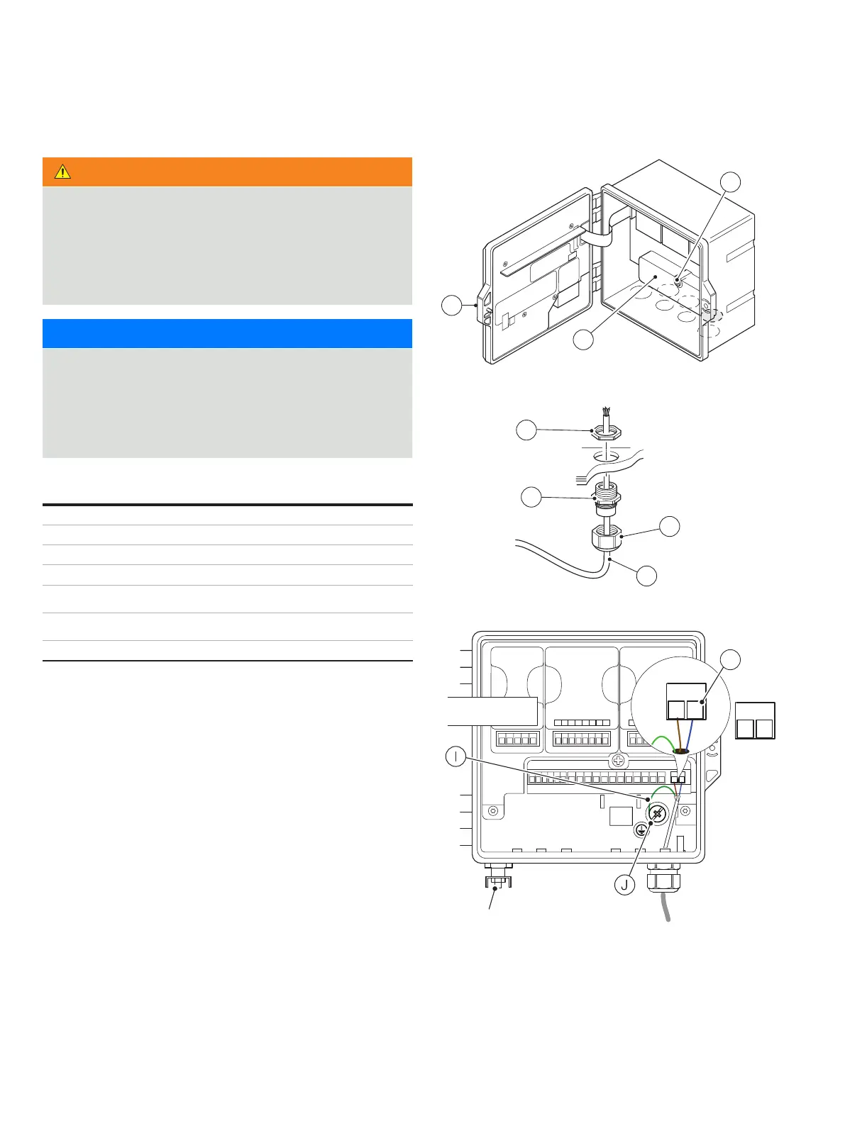
Connecting the transmitter power supply
Referring to Figure 4:
1 Using a suitable screwdriver, release door retaining screw
A and open the transmitter door.
2 Release terminal cover retaining screw B and remove
terminal cover plate C.
3 Fit cable gland D and secure using nut E.
4 Remove gland cover F and route mains power supply
cable G through it.
5 Route the cable through cable gland D and into the
enclosure case.
6 Make connections to the power supply connection
terminals H. Connect earth wire IJ.
7 Tighten gland cover F.
8 Refit terminal cover C and secure it with retaining screw B.
9 Close the transmitter door and secure with door retaining
screw A.
Figure 4 Connecting the transmitter power supply
A
123456 7 8 12345 6 7 8
GLASS
GUARD
REFERENCE
SOLUTION EA RTH
PT
PT
SCREEN
PT (3 rd)
COMMUNICATIONS
Sensor 1
C
B
LN
+ –
D
E
F
G
H
External protective earth stud
version

 Loading...