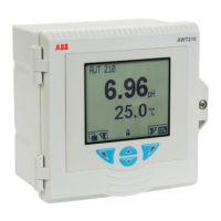
AWT420 | UNIVERSAL 4-WIRE, DUAL-INPUT TRANSMITTER | INF/ANAINST/012-EN REV. A
11
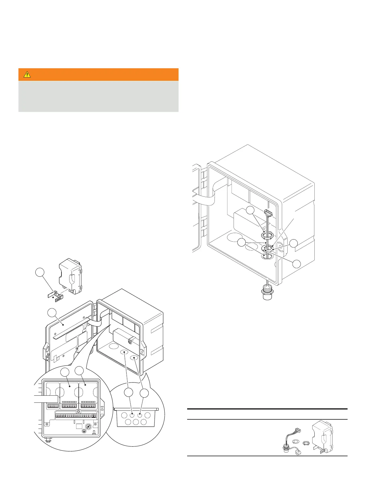
Fitting the hazardous location EZLink bulkhead connector
WARNING
Bodily injury
Up to 240 V AC may be present. Isolate the power supply
before removing the opening the transmitter door.
Referring to :
1 Remove connector block cradle A from EZLink module(s)
and retain for connection.
2 Unlock and open transmitter door B.
3 Fit EZLink modules as follows:
if one EZLink module is used, push-fit it into location C
Note. When fitting the cable assembly, the EZLink
entry D.
module into location C and sensor 2 module into
location E.
Note. When fitting the cable assemblies, the EZLink
entry D and the EZLink bulkhead connector for sensor 2
passes through cable entry F.
Figure 5 EZLink module positions and EZLink cable entries
Referring to :
4 Pass EZLink bulkhead connector cable G through the
5 Pass thread alignment washer H over EZLink bulkhead
connector cable G, ensuring alignment tab I locates into
case slot.
6 Pass thread back nut J over EZLink bulkhead connector
cable G.
Figure 6 Preparing EZLink bulkhead connector cable fixings
EZLink HazLoc connector specification/spares
Power consumption (maximum)
Digital sensor connector IP rating
Fixed length cable
Extension cable (options)
Maximum length (including optional extension cable)
EZLink HazLoc module assembly
Part number
B
A
D
F
D
F
C
E
I
J
GG
H
Flats

 Loading...