Installing an FSO safety functions module
WARNING
Obey the safety instructions given in If you ignore the safety
instructions, injury or death, or damage to the equipment can occur.
If you are not a qualified electrical professional, do not do installation or
maintenance work.
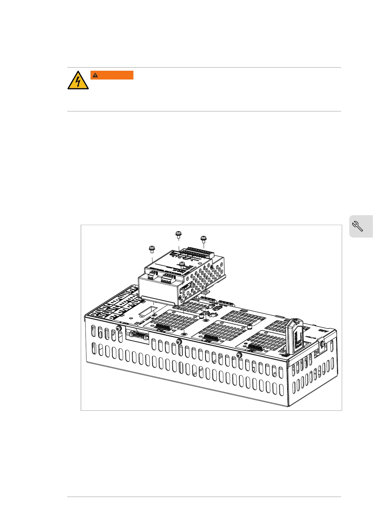
This procedure describes the installation of an FSO safety functions module onto the
BCU control unit. As an alternative, the FSO module can be installed adjacent to the
control unit, which is the standard method for factory-installed FSO modules. For
instructions, refer to the applicable FSO module user's manual.
1. Stop the drive and do the steps in section Electrical safety precautions of the
converter hardware manual.
2. The FSO module comes with alternative bottom plates for installation onto
different control units. For installation onto a BCU control unit, the mounting
points should be located at the long edges of the module as shown in the
illustration below. If necessary, replace the bottom plate of the FSO module.
3. Attach the FSO module onto slot 3 of the BCU control unit [A41] with four screws.
4. Torque the FSO module electronics grounding screw to 0.8 N·m (7.1 lbf·in).
Note: The screw tightens the connections and grounds the module. It is essential
for fulfilling the EMC requirements and for proper operation of the module.
5. Connect the FSO module data cable between FSO connector X110 and BCU
connector X12.
6. To complete the installation, refer to the instructions in the applicable FSO module
user's manual.
Mechanical installation 19
 Loading...


