Document: v0.6 / Document No.: 6AGA000008-0102-EN | Date: 22-05-2019 Page 19 of 23
4.4 Technical functioning
4.4.1 Normal operation
Normal positions of the different switches and breakers when the charger is in operation (idle;
not charging):
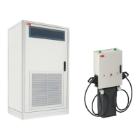
Power Cabinet
• Main switch (A): Vertical (“1”)
• MCB (Q17) AC power supply for ACM (B): up
• RCD (Q13) control (C): up
• RCD (Q12) redundant control (D): up
Depot Charge Box
• SPD (F2) AC Power Supply: green
• MCB (F1) AC Power Supply: up
• Fuse (F3,F4) DC Precharge Circuit: not blown
• SPD (F5) DC Power Circuit: green
4.4.2 Switch the charger system on/off
In case it is necessary to switch off the charger system, this can be done by turning off the
main switch (A in Power Cabinet, see section
Component overview Power Cabinet
on page 18):
1. Open the front door.
2. Locate the main switch (A).
3. Turn the handle counterclockwise to the horizontal position, marked with “0”.
Switching off the charger does not switch off Depot Box. Each box has its own
power supply. To turn off the Depot Box see chapter 4.4.3
To switch the charger back on, turn the handle clockwise to the vertical position, marked with
“1”. After about a minute the indicator light (beacon) will turn green.
4.4.3 Switch the depot box
In case it is necessary to switch off the depot box, this can be done by turning off the main
switch:
1. Open the front door.
2. Locate the main switch (B).
3. Move the MCB switch down (OFF position). Green painting on the switch should be
visible

 Loading...