LST300 | COMPACT ULTRASONIC LEVEL TRANSMITTER | LST300–EN REV. E
39
7 Advanced functions
Signal waveform
The signal waveform function is used to analyze the process
conditions, optimize installation and visualize false echoes for
further processing. The signal waveform is available on the
Through The Glass (TTG) version of LST300, but can also be
accessed via Enhanced Device Description (EDD) on handheld
configurators such as ABB DHH800, or on a computer using the
Device Type Manager (DTM).
In the instructions below, the signal waveform on the LST300
HMI interface is shown as an example.
Accessing the waveform display
1 Log on to the LST300 at the Standard or Advanced level.
2 Select Diagnostics from the main menu.
3 Select Waveform from the “Diagnostics” submenu.
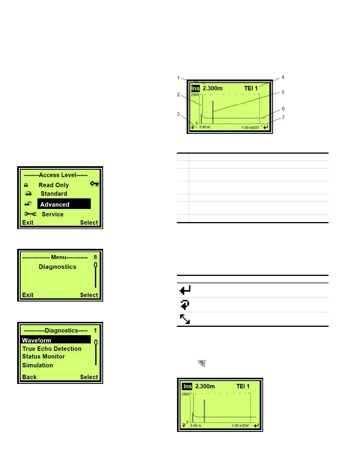
Signal waveform display
Figure 25 Signal waveform display (example)
Current process values
Blanking distance line — All signals to the left of this line are ignored
Waveform x-axis offset — Used to scroll along the axis when
zoomed
True Echo Index — Indicates which echo is used when True Echo
Detection is used
Echo signal example
Threshold — All signals below this line are ignored and considered
noise
Waveform zoom level — Used to see more details.
The signal waveform can be selected from the “Diagnostics”
menu. It shows information about the last measured signal and
the current process values. The zoom function allows access to
more details in a specific region.
Description of symbols
Symbol Description
Return to the “Diagnostics” menu
Scroll to the next parameter
Enter the True Echo Index selection menu
Selecting paramaters to display
In the signal waveform display, select the live information to
display as follows:
1 Press
to switch until the current process values box in the
top left is highlighted.

 Loading...


