28
MOUNTING AND OPERATION MANUAL INDOOR AIR SWITCH-DISCONNECTOR, NAL/NALF/VR
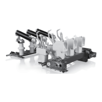
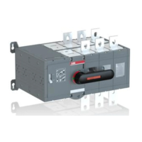
12.1 Replacing the mechanism on the switch.
The mechanisms are mounted on the right hand
side of the switch main frame and the switch is
normally operated from the same side
(mechanism-side). When the switches have to be
operated from the opposite side, an operating
shaft must be connected, see Fig. 38. The
mechanism clutch is brought together with the
clutch of the hollow main shaft and the
mechanism is fixed to the switch frame. Usually
the switch disconnector is delivered without
shaft extension for left hand side operation.
—
12.0 Replacing the mechanism on
the switch
1 / 1
1:4
A3
Sheet No.
Format
Language
Scale
Subtitle
Type
Derived from
Name
Date
Location
Revision
Drawn
Checked
Approved
EC No.
EN
Drawing status
Title
Drawing No.
Responsible
ABB Switzerland Ltd
Weight
Material
f
m
c
v
H
L
K
PROPRIETARY AND SECRET INFORMATION
The information contained in this document has to be kept strictly confidential.
Any unauthorized use, reproduction, distribution or disclosure to third parties
is strictly forbidden. ABB reserves all rights regarding Intellectual Property Rights.
Thread Quality Tolerance
"6g-6H" ISO 965
ISO 2768 T.1 Lengths and Angle
ISO 2768 T.2 Geometrical Tolerances
Surface
Surface code
Coord. punching N.C.Mach.
and unfold JS11
Standard Tolerances for Machining and Forming
© Copyright
ABB. All rights reserved.
2016
D
C
8
A
B
E
8
7
6
5
4
3
2
1
A
B
C
D
E
7
6
5
4
3
2
1
Group Technology Management
—
36 Mounting of shaft extension for left hand side operation
—
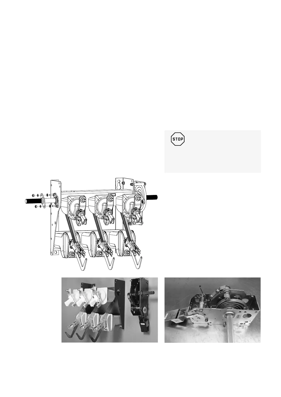
37 Shunt trip mounted on the A-mechanism
—
38 Mounting the mechanism on the switch
_
WARNING!
These operations shall be carried out by
authorised personnel only!
 Loading...