________________________________________________________________________________________________________
AC500-eCo - 12 -
Hardware Introduction
2.2 S500-eCo I/O Modules Overview
The S500-eCo I/O modules are with compact housing for DIN-Rail or wall mounting. It has the
same height and depth as the standard S500 modules and can be used or mixed with the
standard S500 I/Os on all AC500 CPUs.
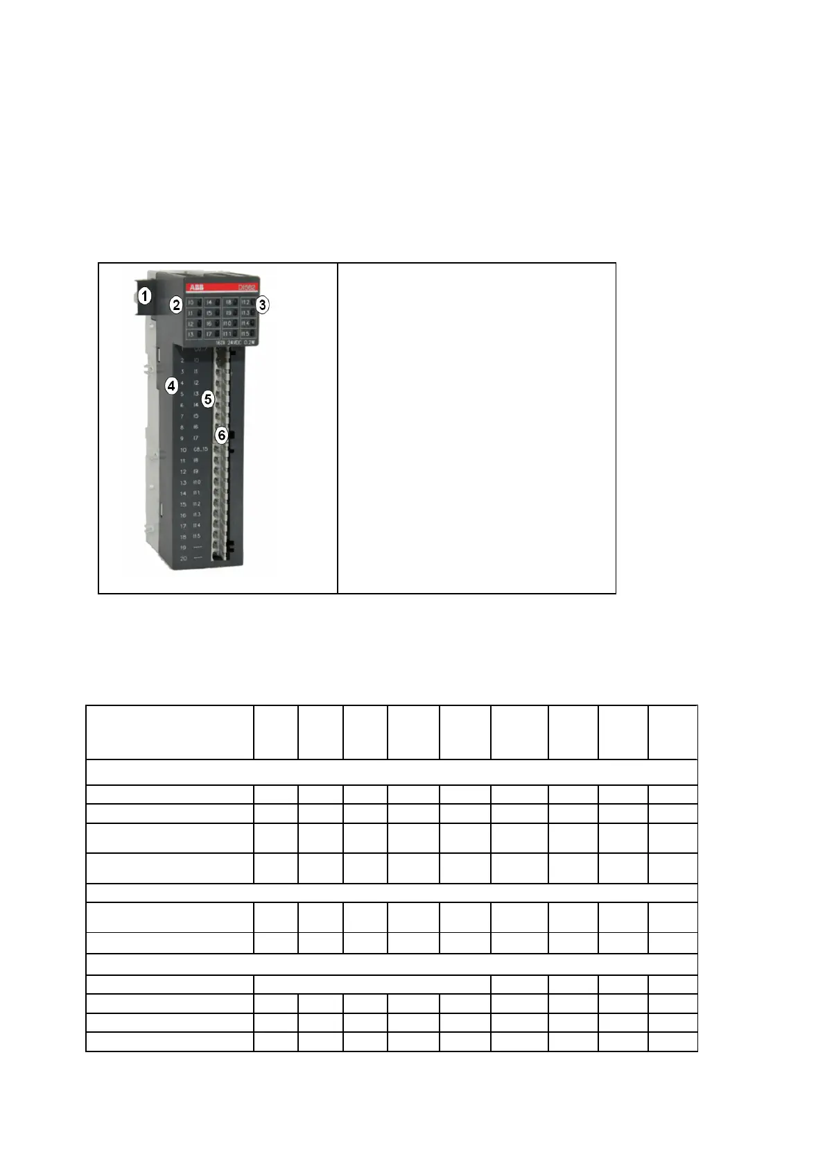
2.2.1 I/O Unit components
1. I/O-Bus
2. Allocation of signal name
3. 16 yellow LEDs to display the
signal statuses
4. Allocation of terminal number
5. Allocation of signal name
6. 9 and 11 poles I/O terminal block
(screw-type terminals)
2.2.2 S500-eCo I/O Modules Assortments
Digital I/Os overview
DI
561
DI
562
DI
571
DO
561
DO
571
DO
572
DX
561
DX
571
DC
561
Number of Channels per Module
Digital Inputs DI 8 16 8 - - - 8
8 -
Digital Outputs DO - - - 8 8 8 8
8 -
Configurable as Input or
Output DC
- - - - - -
16
Relays (R) / Transistor (T) - - -
T
R
Triac
(AC)
T R T
Process voltage
AC - -
100~
240
-
100~
240
100~
240
- - -
DC 24V 24V - 24V 24V - 24V
24V 24V
Channels additional configurable as:
Fast Counter Max. 2 channels per module - X
- -
Puls-Width-Modulation - - - - - - X
- -
Revolution-/time- + frequency
- - - - - - X
- -
Interrupt I/O - - - - - - X
- -