________________________________________________________________________________________________________
AC500-eCo - 17 -
Hardware Introduction
3.2 Wiring
Wiring cautions
4.1
• Do not lay I/O signal cables next to power cables or allow them to share the same trunk duct.
Low voltage cables should be reliably separated or insulated with regard to high voltage cabling.
• Where I/O signal lines are used over an extended distance consideration for voltage drop and
noise interference should be made.
• Do not lay signal cables near high voltage power cabling or cabinet housing along the same
trunk duct. Effects of noise or surge induction may occur.
• Replace the terminal cover provided, after installation or wiring work is completed, and before
supplying power and operating the unit to avoid electric shock.
• When performing incorrect wiring or operation, serious damage will occur.
3.2.1 Power Supply Wiring
AC500 CPUs PM554 and PM564 use two kinds of power supply voltage:
1. 24VDC
2. 100~240VAC.
IMPORTENT
For 24V DC variant, exceeding the maximum power supply voltage (>30V DC)
for process or supply voltages could lead to unrecoverable damage of the
system. The system could be destroyed.
CAUTION
Removal of energized modules is not permitted. All power sources (supply
and process voltages) must be switched off while working on any AC500
system.
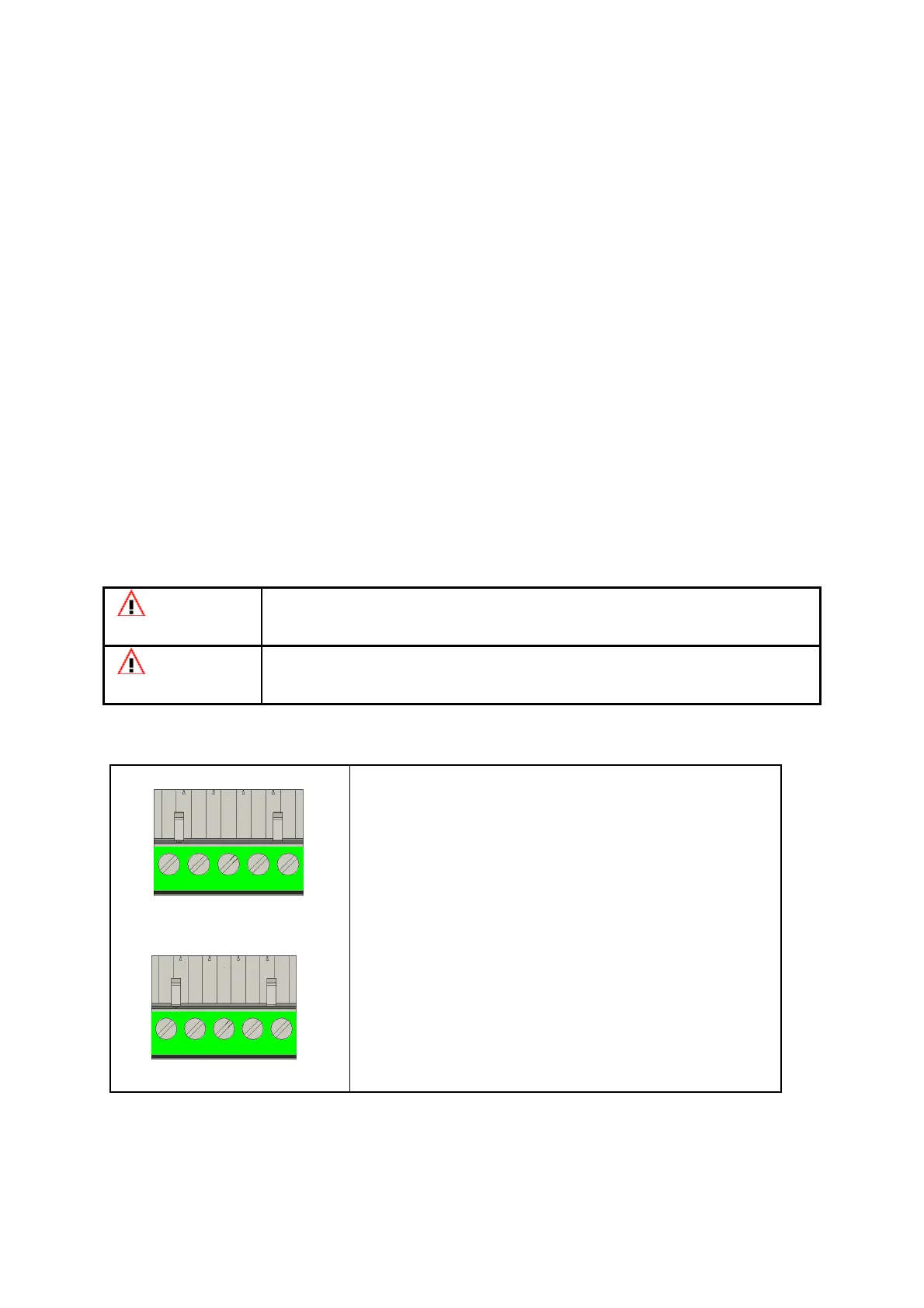
24V DC
L+ M FE L+ M
24V 0V FE 24V 0V
100-240V AC
The supply voltage 24V DC is connected to a 5-pin
removable terminal block. The 5 pins from left to right
are L+, M, FE, L+ and M. L+ and M exist twice, so it is
possible to supply external sensors from this terminal.
FE is for functional earth.
The supply voltage 100~240V AC is also connected
to a 5-pin removable terminal block. The 5 pins from
left to right are L, N, FE, L+ and M. FE is for functional
earth. L and N are connected to AC power supply
source. L+ and M are internal voltage outputs 24V DC
and 0V. They are used for external modules.
L N FE L+ M
0V FE 24V 0V
100~240
 Loading...