________________________________________________________________________________________________________
AC500-eCo - 13 -
Hardware Introduction
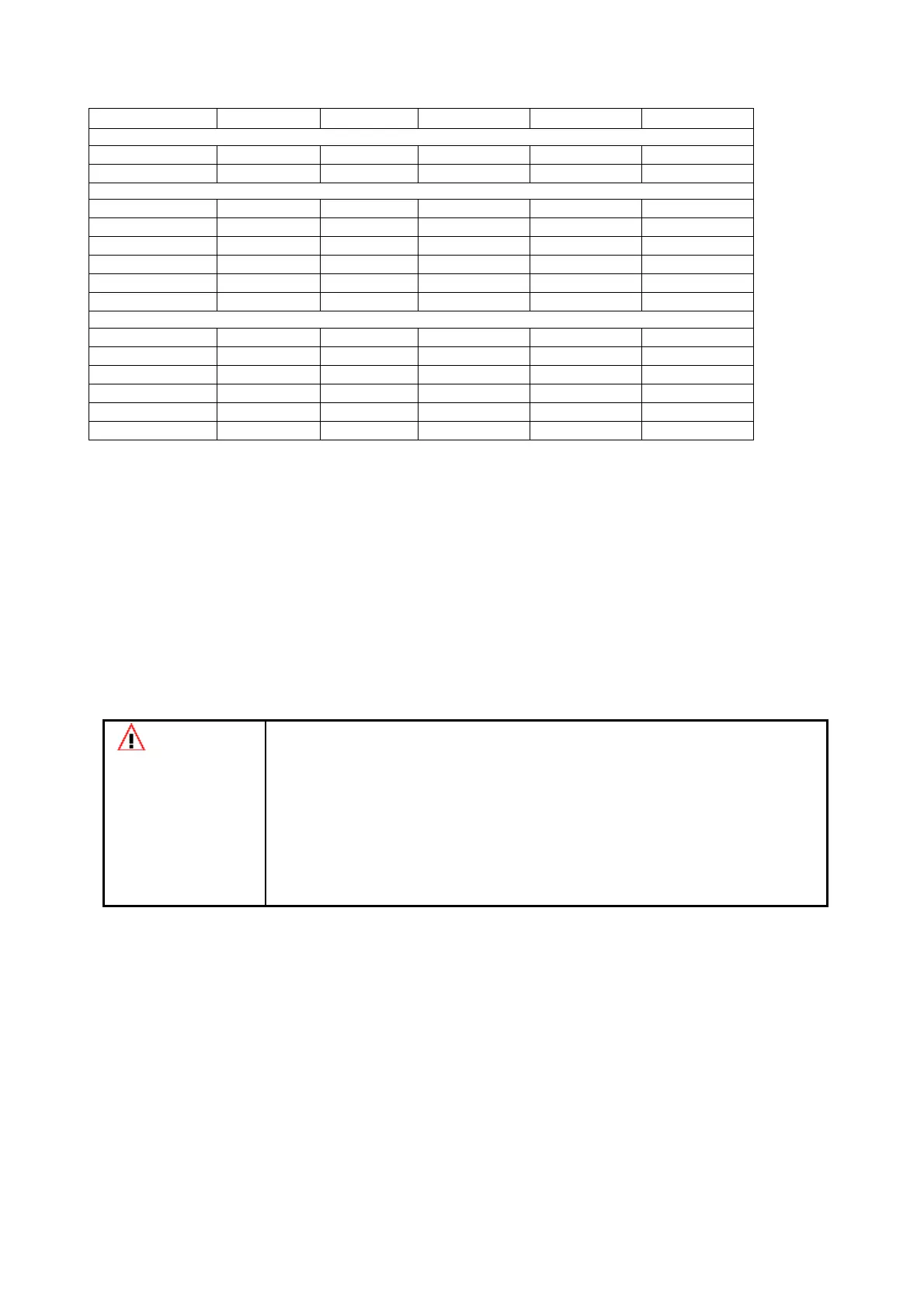
Analog I/Os overview
AI561 AO561 AX561 AI562 AI563
Number of Channels per Module
Analog Inputs 4x - 4x - -
Analog Outputs - 2x 2x - -
Inputs, single configurable as
-2.5V…+2.5V x - x - -
-5V…+5V x - x - -
0…5V x - x - -
0…10V x - x - -
0…20mA x - x - -
4…20mA x - x - -
Outputs, single configurable as
-10V…+10V - x x - -
0…20mA - x x - -
4…20mA - x x - -
Inputs
RTD - - - 2x -
Thermo Couple - - - - 4x
3. Hardware Installation and Wiring
This Chapter provides general precautions for using the AC500 and related devices.
The information contained in this chapter is very important for the safety and reliability of the
applications.
ATTENTION
Preventing Electrostatic Discharge
This equipment is sensitive to electrostatic discharge, which can cause internal
damage and affect normal operation. Follow these guidelines when you handle
this equipment:
Touch a grounded object to discharge potential static.
Wear an approved grounding wrist strap.
Do not touch connectors or pins on component boards.
Do not touch circuit components inside the equipment.
If available, use a static-safe workstation.
When not in use, store the equipment in appropriate static-safe packaging.
System planning
Consider the following when planning your AC500 system:
•
The AC500 CPU can be powered by 24V DC or 100-240V AC.
•
The AC500 CPU PM554 and PM564 support as many as 7 local I/O expansion modules.
•
An additional process power supply has to be provided for the I/O modules of each module.
Each I/O expansion module can be powered with its own power supply (for isolation
purposes) or the same power supply can also be used.
 Loading...