1SFC132374M0201 5
2.2 MTQ22-FBP
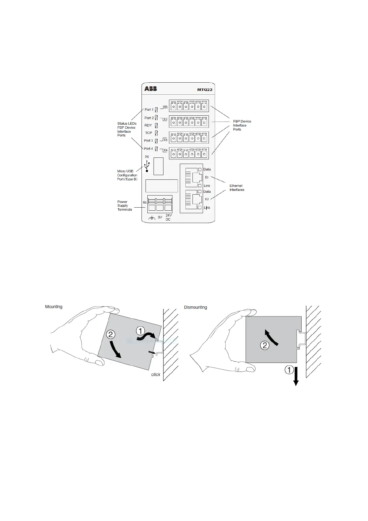
A device layout of the MTQ22-FBP can be seen in Figure 1. Connectors X1 ... X4 are used to connect up to four
FBP devices to the MTQ22-FBP. On the left side of the port connectors LEDs show the current communication
status. See chapter 5 for detailed information regarding status LEDs.
Figure 1: Top view of the MTQ22-FBP. Four PSE devices can be connected to the MTQ22 via the ports X1 to X4. The
standard Micro USB connector X5 allows to configure the device.
The Micro USB connector X5 allows device configuration using a PC, see chapter MTQ22-FBP. Two RJ45
sockets E1 and E2 offer Ethernet connectivity. The communication status of each interface is shown by two
LEDs. The MTQ22-FBP must be supplied with 24VDC via X6.
Mounting and Dismounting
You can mount and dismount the MTQ22-FBP onto a 35 mm standard mounting rail, without tools.
Arrange the communication cables as far away from the motor cables as possible. Avoid parallel runs. Use
bushings at cable entries. The network cable is connected to the RJ45 connectors on the MTQ22-FBP module.
Standard CAT5 UTP, FTP or STP cables can be used. The shield of the RJ45 cable is connected to the shield of
connector X6.

 Loading...