54 Service PSTX470...570 | Service Manual | 1SFC13105M0201
4.4.1 Change the PCBA
CAUTION
Always make sure that the power supply is
switched off before doing maintenance on the
Softstarter.
WARNING
When performing maintenance on the Softstarter,
an antistatic strap must be used. The antistatic
strap should be worn on the wrist, and be
connected to an electrical ground, to prevent
electrostatic discharge (ESD) damage to the
Softstarter.
DISMANTLE THE SOFTSTARTER
Remove main power cables and control
cables
Disconnect the main power cables and the control
cables as described in chapter 4.3.3, step 1-3.
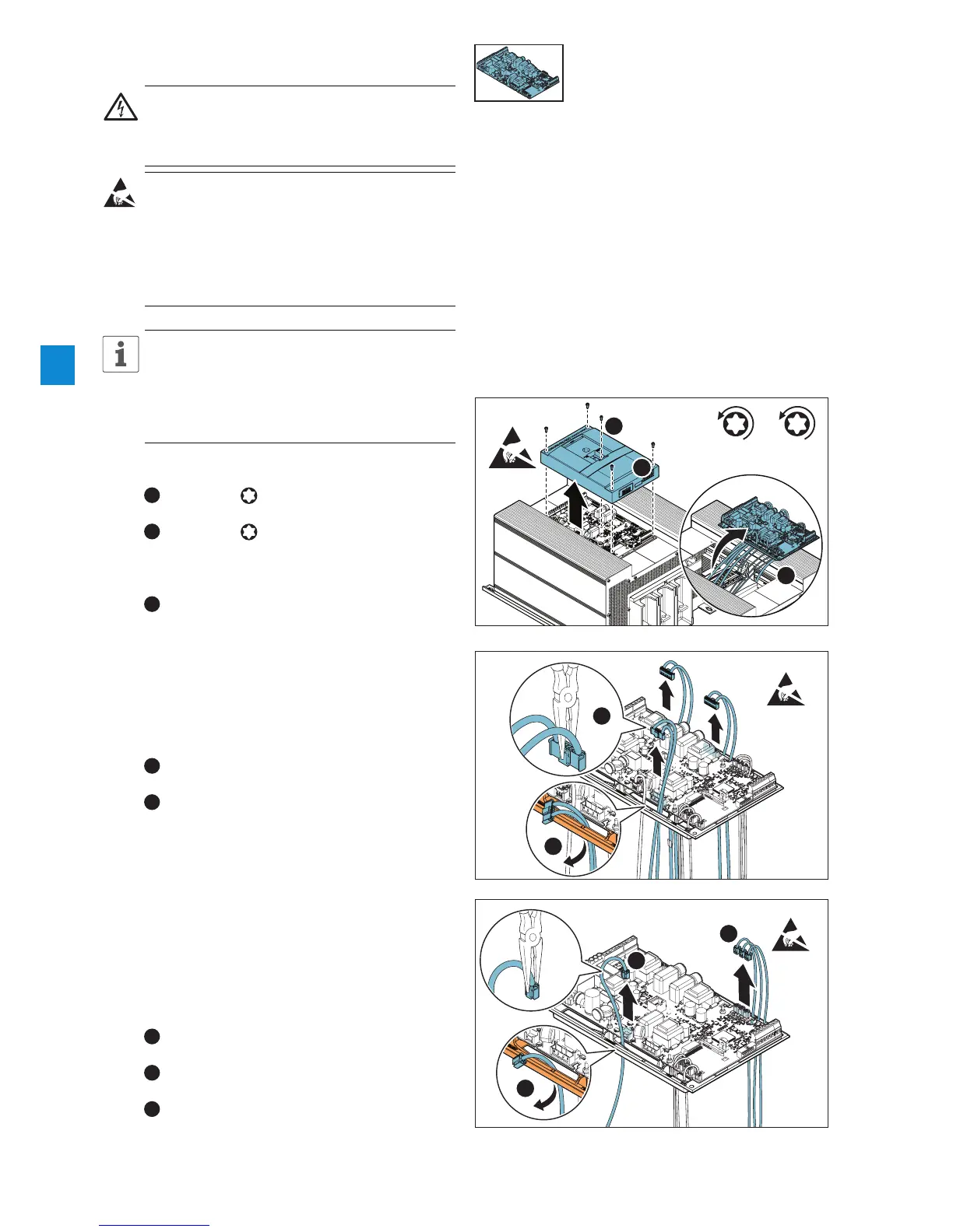
1. Remove front cover
1
Loosen (1x) Torx 15 M3,5x12 on the HMI
bracket.
2
Loosen (4x) Torx 20 M4x12. Remove the
front cover by lifting it upwards from unit. Ensure
that screws do not come loose and fall down on
the PCBA upon removal.
3
Lift out the PCBA from unit (at this point still
mounted on bracket) to facilitate continued service.
2. Disconnect SCR cables from PCBA
Mark the SCR cables with 1, 2, 3 prior to
disconnecting them to ensure proper re-
connection. Note that markings are to be made
in accordance with existing data available on the
PCBA bracket.
1
Disconnect the three SCR cables from their
terminals on the PCBA using a long-nose plier.
2
Pull out the three SCR cables from the cable
inlets on the PCBA bracket.
3. Disconnect bypass contactor cable and CT
cables from PCBA
Mark the CT cables with 1, 2, 3 prior to
disconnecting them to ensure proper re-
connection. Note that markings are to be made
in accordance with existing data available on the
PCBA bracket.
1
Disconnect the bypass contactor cable from its
terminal on the PCBA using a long-nose plier.
2
Disconnect the three CT cables from their
terminals on the PCBA using a long-nose plier.
3
Pull out the bypass contactor cable, and the
three CT cables, from the cable inlets on the PCBA
bracket.
Tx 20
M4 x 12
Tx 15
M3,5 x 12
1
4.4.1_1
1
2
3
2
4.4.1_2
1
2
3
4.4.1_3
1
3
2

 Loading...