8
EN
(Continue to next page)
Available components for wiring box (02) Quantity
Multifunction relay, aux relay and
RS-485 connector
(pre-installed on communication
board (28))
4
Remote ON/OFF connector
(pre-installed on communication
board (28))
1
Two-hole gasket for M25 signal ca-
ble glands (12) and cap
1 + 1
Fuse holder for positive string
fuses (19)
24
Positive string fuses (19)
(gPV - 1000Vdc - 15A)
24
A4 1:1 1/1
South Africa network standard label for
PVS-120-TL (SIRIUS)
LABEL MATERIAL: 3M type 7331 (UL R/C, PGJI2)
INKS: Refer to UL File MH16411
LABEL CONTENT: Fixed as shown in the picture
SIZE: 45 mm (height) x 90 mm (width)
A.Statuti
G.Iannuzzi
S.Soldani
S.Bindi
WARNING!
NRS 097-2-1:2017 (South Africa)
09/04/2018
09/04/2018
09/04/2018
09/04/2018
XLP.V2Q10.0AL
AA
It is not intended to connect this Inverter to a network with an higher
Network Impedance.
Reference Impedance
Fault Level
0.156
1475
Total [Ω ]
I_SC [ A ]
3.9
1018
X/R ratio
S_SC [kVA] (three phase)
All
material
used
and finished prod uct, must meet the r equirements of the curr ent RoHS
rect i
i
ve 2002/95/EC.
Title
Issued
Modified
D
D
esign approved
Elec. Eng. ap proved
Mfg. approved
Size Scale Di m. in mm Sheet Drawing No. Revision
© Copyright 2018 Power-One Italy Spa. All rights reserved. Reproduction, use or disclosure to third parties without express written authority is strictly forbidden.
South africa network standard label 1
Key tool for front cover quarter cam-
lock
1
In addition to what is explained in this guide, the safety and installation information provided in the installation manual must be read and followed.
The technical documentation and the interface and management software for the product are available at the website.
XXXXXXXXXXXXXXXXXXX
XXXXXXXXXXXXXXXXXXX
ABB solar inverters
Technical documentation -
Available components for power module (01) Quantity
Coupling screw between wir-
ing box and power module
2
M16 screws with washer to
clamp internal AC cables on
AC interconnection board (58)
3
M5 hex nuts + M5 serrated
lock washers to clamp internal
earth cable to the power mod-
ule
1 + 2
In addition to what is explained in this guide, the safety and installation information provided in the installation manual must be read and followe
The technical documentation and the interface and management software for the product are available at the website.
XXXXXXXXXXXXXXXXXXX
XXXXXXXXXXXXXXXXXXX
ABB solar inverters
Technical documentation -
Available components for bracket Quantity
M8 screws with washers for
mechanically securing the half-
brackets
2
M6 screws for mechanically se-
curing the wiring box to the
bracket
2
—
List of supplied components
General recommendation on installation position
• See characteristics and technical data paragraph to check the required environmental conditions (protection rating, temperature,
humidity, altitude, etc.).
• The installation location shall be easily accessible.
• Installation of the unit in a location exposed to direct sunlight is NOT acceptable (add awning in case of direct sunlight installation).
• Final installation of the device must not compromise access to any disconnection devices that may be located externally.
• Do not install in small closed rooms where air cannot circulate freely.
• Always ensure that the flow of air around the inverter is not blocked so as to prevent overheating.
• Do not install in locations where flammable substances or gases may be present (minimum distance 3 m).
• Do not install on wooden walls or other flammable supports.
• Install on a wall or strong structure suitable to bear the weight.
• Do not install in rooms where people live or where the prolonged presence of people or animals is expected, because of the high noise
that the inverter produces during operation. The level of the sound emission is heavily influenced by where the appliance is installed
(for example: the type of surface around the inverter, the general properties of the room, etc.) and the quality of the electricity supply.
• Never open the inverter in the case of rain (even light rain), snow or a level of humidity >95%. Always carefully seal all unused openings.
In case of opening when the unit is wet, avoid any water infiltration inside the unit, either in WB or PM.
• All installations over 6500’ (2,000 meters) must be assessed by ABB Technical Sales to determine the proper datasheet derating.
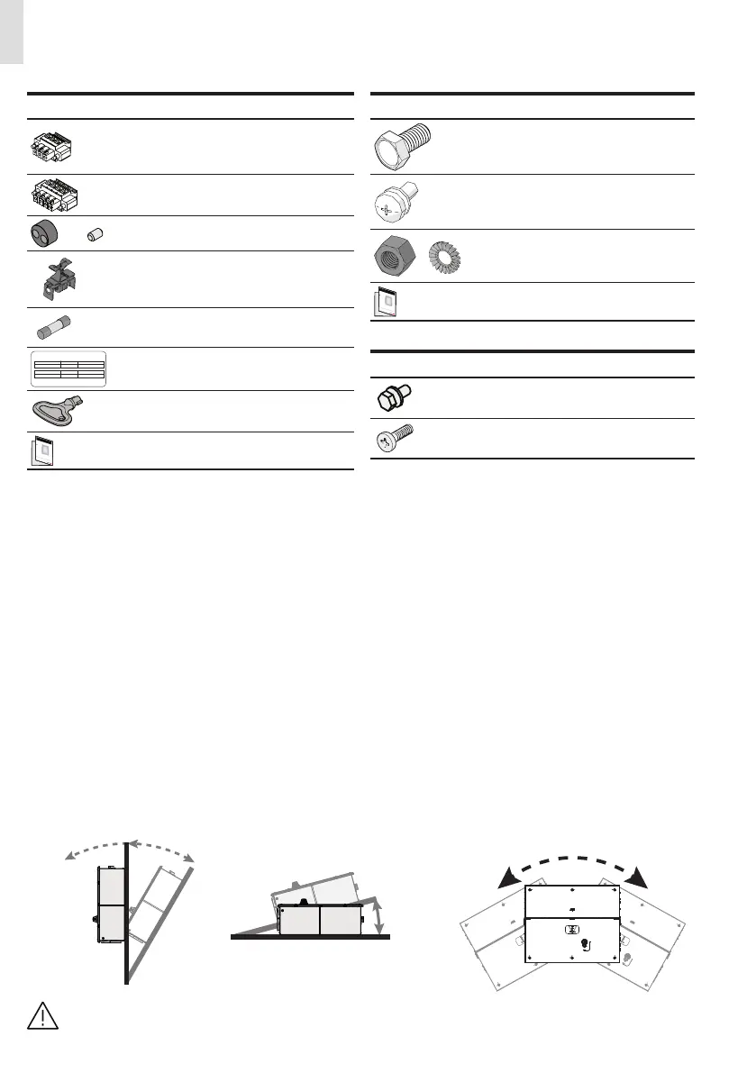
Tilting admittance
• The installation can be carried out vertically or horizontally, with a maximum inclination as indicated in the figures.
Vertical Tilting Horizontal tilting Side Tilting
NO
OK
30° MAX
OK
30° MAX
±1° MAX
PVS-120
In case of horizontal installation in outdoor environment consider an installation with a minimum tilt of 3° to avoid
any water stagnation.
—
Choice of installation location
 Loading...


