19
EN
—
Grid output connection (AC side)
(Continue to next page)
The inverter must be connected to a three-phase system with the center of the star connected to earth. To connect the inverter to
the grid is possible to choose between the four-wire connection (3 phases + neutral) and the three-wire connection (3 phases).
In any case, the inverter’s earth connection is mandatory.
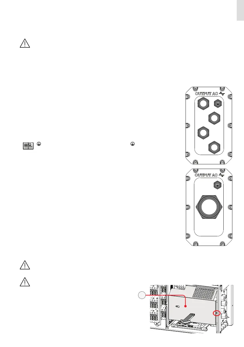
Depending of the type of the AC panel it’s possible to use single conductors cables or a multipolar cable:
• Single-core configuration have 4xM40 cable glands for the ”N” neutral, “R”, “S”, “T” phases and a M25 cable gland for the earth ca-
ble.
• Multi-core configuration (optional) have a M63 cable gland for the ”N” neutral, “R”, “S”, “T” phases and a M25 cable gland for the
earth cable.
The connections can also be made with the wiring box (02) detached from the power module (01) which can be connected later for
commissioning.
FOLLOW THE PROCEDURE BELOW TO ROUTE ALL THE REQUESTED CABLES:
The installation must be performed by qualified installers and/or licensed electricians in accordance with the ex-
isting regulations in the country of installation and in accordance of all safety rules for performing electrical
works. The customer has civil liability for the qualification and mental or physical state of the personnel who inter-
act with the equipment. They must always use the personal protective equipment (PPE) required by the laws of the
country of destination and whatever is provided by their employer.
Before carrying out any operation, check that any external AC switch downstream to the inverter (grid side) are in
OFF position applying LOTO procedure on it.
• Open the wiring box front cover (07).
• Remove the AC protective shield (27) by removing the M5 screw.
• Single-core configuration (default):
In this configuration the AC output and earth cables must be inserted into the proper cable
glands, trying to follow a logical order based on the position of the internal connections:
R = Phase R (indicated with a label near the AC connection busbar (21))
S = Phase S (indicated with a label near the AC connection busbar (21))
T = Phase T (indicated with a label near the AC connection busbar (21))
N = Neutral (indicated with a label near the AC connection busbar (21))
The earth connection can be made using the Protective earth point (int.) (25) or Protective
earth point (ext.) (10) or both (this is required by regulations in force in certain countries of in-
stallation).
= Earth (indicated with the protective earth symbol near the protection earth
connection point (int.) (25) or protection earth connection point (ext.) (10)).
R
S
T
N
• Multi-core configuration (optional):
This version of the AC panel (11) can be ordered separately.
R
S T
N
27
 Loading...


