23
EN
(Continue to next page)
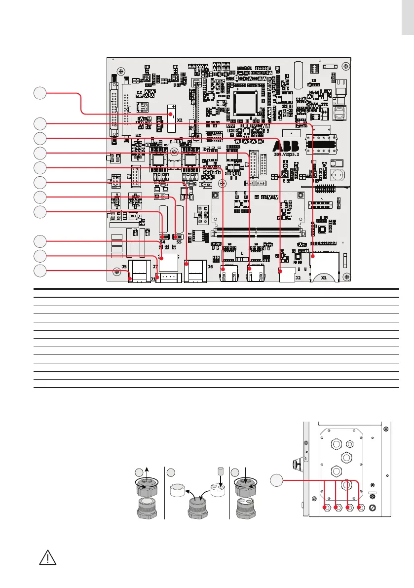
Communication and control board references
J2 X1
X2
S5S4
J7
J1
J5 J6
1
2
1
8
7
432
ZGN.V2Q15.2
33
37
36
34
35
38
39
40
41
42
43
Terminal name Terminal reference Description of communication and control board (28)
J5 33 Multifunction relay connector (ALARM terminal block)
S4 34 RS-485 ABB service 120Ohm termination resistance switch (ABB service only)
S5 35 RS-485 line 120Ohm termination resistance switch
J7 36 RS-485 connector (RJ45) (ABB Service only) (*)
J1 37 Remote ON/OFF terminal block (*)
J6 38 RS-485 line terminal block
- 39 Ethernet connector 2 (RJ45)
- 40 Ethernet connector 1 (RJ45)
J2 41 USB connector
X1 42 SD card slot
X2 43 CR2032 Coin battery
(*) The RS-485 connector (RJ45) (ABB Service only) (36) and the signal R1 on the Remote ON/OFF terminal block (37) are used to
bring the signals on the external connector RS-485&Rem.ON/OFF (57).
Connections to the communication and control board
The communication and control signals are connected to the communication and
control board inside the DC wiring box or directly to the connectors on the external
of the inverter. In particular, on the left side of the DC wiring box, there are 4xM25 ca-
ble glands (12) that can be used to reach the terminals / connectors on the commu-
nication and control board. Each cable gland accepts a cable (from 10 mm to 17 mm
diameter).
As an alternative to each cable
gland internal gasket the two-
hole gasket (supplied) could be
installed:
The two-hole gasket accepts two
cables with a diameter of 6mm; if
a seal hole is not to be used, it is
necessary to install a plug (sup-
plied plastic cylinder) to ensure
the inverter’s sealing.
SERVICE ONLY
12
• Please ensure that all unused cable glands (12) are properly sealed by the IP65 plastic cap.
• Check the tightness of the signal cable glands (12) at the end of wiring operations.
Make sure the cable glands are properly sealed to ensure to keep IP65 protection degree.
—
Connection of the communication and control signals
 Loading...


