24
EN
(Continue to next page)
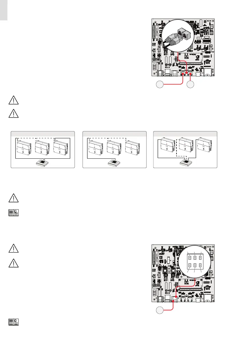
Ethernet connection
The ethernet connection allows a direct data transfer to the ABB server for moni-
toring purpose. When the inverter will be powered on, network parameters are au-
tomatically set and the inverter starts transmissing telemetry data to the Aurora Vi-
sion® CLOUD platform.
The connection of the ethernet communication cable must be made on the spe-
cific connectors (39)(40) located on the communication and control board (28).
If the inverters of the plant need to be connected in daisy chain or ring configura-
tion use both connectors.
The cable should be compliant to the following specification:
• Cable type: Patch or Cross type, 100BaseTx, CAT5e (or higher). For outdoor appli-
cation and/or in presence of strong electromagnetic sources it is advisable to use
shielded cables with metallic shielded RJ-45 plug.
• UV-resistant if used outdoors.
• Type of plug: metallic shielded RJ45.
• The maximum length that can reach these cables is 100 meters, and it is always
advisable not to let them pass by the power cords to avoid interference with data
transmission.
• Maximum inverters number connected over one single daisy chain is 40.
J2 X1
X2
S5S4
J7
J1
J5 J6
1
2
1
8
7
432
ZGN.V2Q15.2
39 40
For outdoor application and/or in presence of adverse weather/strong electromagnetic events it is advisable to
use additional overvoltage protective devices.
In order to avoid earth loop (that could create communication issues) the shield of any Ethernet cable must be con-
nected to the RJ45 plug in only one side, the other side of the shield should be leaved floating. This could be guar-
anteed by crimping the shield or the screen of the ethernet cable to the RJ45 connectors only at one end of each ca-
bles.
Three topologies of ethernet connection to the router are available:
Ring configuration
ROUTER
Daisy chain configuration
ROUTER
Star configuration
ROUTER
The ring configuration is the preferred method to connect multiple units in order to allow reaching inverters also in case of single
unit failures.
In case inverters are connected to the networking switch with a ring topology is recommended to enable SPT protocol on the
switch (Spanning Tree Protocol SPT (IEEE 802.1D) is enabled by default on inverters).
No initial setup is required to start data transmission to Aurora Vision.
Internet connection is required to use all the Aurora Vision remote functionalities.
Please refer to Aurora Vision documents available on ABB website for further information how to get an Aurora Vi-
sion account for remotely monitoring and managing the installed solar assets.
Connection of RS-485 serial communication line
Please note that automatic settings of network parameters at turning
on, embedded logging capability, automatic logger-free transferring
of data to Aurora Vision Cloud and remote firmware update are pro-
vided over TCP/IP (Ethernet and/or Wi-fi) bus only.
The use of the inverters over the RS-485 line is recommended in case of
monitoring and controlling by using third party RS-485 control sys-
tems.
The RS-485 serial communication line is reserved for the connection of the inverter
to monitoring devices that communicate with the Modbus communication proto-
col (Modbus/RTU SUNSPEC compliant). The RS-485 serial communication line is
available on the communication and control board (28) with two terminal blocks
(38) for each serial line signal (+T/R, -T/R and RTN) so as to be able to make a daisy-
chain connection (“in-out”) of multiple inverters.
The RS-485 port (38) can either be used for connecting supported accessories (like
weather station): in this case data from accessories will be logged and transferred
to the cloud by inverter itself (master mode). This allow to use the inverter as logger
also for ABB accessories.
For further information regarding the configuration and use of the RS-
485 serial communication line, please refer to the user manual.
J2 X1
X2
S5S4
J7
J5 J6
1
2
1
8
7
432
ZGN.V2Q15.2
38
 Loading...


