23
4. Press to enter the setting mode and give the password, if required. If the
default password 999 is still valid, no password is required.
5. The first digit of the setting value of the parameter to be edited starts to flash.
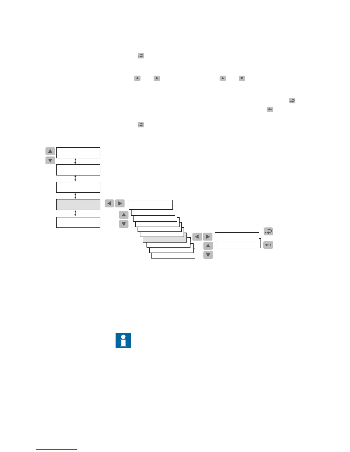
Use
and to move the cursor and and to increase or decrease the
value. The setting range (for example Year or Minutes) is shown on the right-
hand side of the second line of the display.
6. To store a new value and return the display to the view mode, press
.
7. To exit the setting mode without storing the changes, press
once before
confirming and the display is returned to the view mode.
8. Press
to return the display to the idle mode.
TRIP CIRCUIT SUP
Main Menu
Group Menu
Parameter Menu
Confirm
Cancel
SETTINGS
CONFIGURATION
MEASUREMENTS
RECORDED DATA
FUNCTION TEST/DI
COMMUNICATION
LANGUAGE
FREQUENCY
CONFIGURATION
CONFIGURATION
MEMORY SETTINGS
HMI PASSWORDS
TIME
RTD INPUTS
INFO
YY-MM-DD (00-23)
hh.mm;ss (00-59)
STORE COUNTER
A040237_2
Fig. 4.1.9.-1 Setting the real-time clock
4.1.10. How to switch between front and rear connecti on
There are two means of serial communication available for the relay: the front
connection for SPA bus communication and optional rear communication modules
for communication via the SPA bus, IEC 60870-5-103, MODBUS (RTU or ASCII)
protocol.
If the relay is not provided with an optional rear communication
module, or if the module has been disabled, the front connection is
always active and switching between front and rear connection is not
allowed.
If the optional rear communication module is installed and enabled, the default
setting is the rear connection. Switch between front and rear connection as follows:
Motor Protection Relay
Operator's Manual - ANSI ve rsion
REM 610REM 610
1MRS755538