55
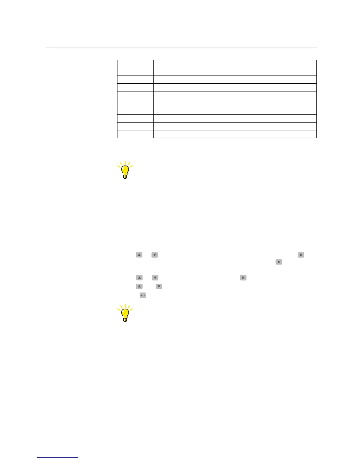
Table 5.4.-1 Function test (Continued)
Number Function
12 Trip of element 46
13 Trip of element 46R
14 Motor start up
15 External trip
16 Alarm of element 49/38-1
17 Trip of element 49/38-1
18 Alarm of element 49/38-2
19 Trip of element 49/38-2
0 IRF
It is also possible to test the output contacts via serial communication
by using the O parameters.
5.5. Digital input test
This section describes how the availability of signals connected to the digital inputs
can be tested.
To monitor the status of the digital inputs, navigate in the HMI menu as follows:
1. Press an arrow button to access the main menu.
2. Use
or to select CONFIGURATION in the main menu and press . The
cursor is at the first menu item, FUNCTION TEST/DI. Press
again to enter
the test menu.
3. Use
or to select DI STATUS and press to see the status of DI1.
4. Use
and to monitor the state of the other four digital inputs.
5. Press
to return the display to the idle mode.
It is also possible to read the state of the digital inputs via serial
communication.
5.6. Testing protection functions
The short-circuit and ground-fault protection functions in the relay can be tested
with the setting values used during normal operation. If other settings are used
during testing, make sure that the original settings are re-entered after the test is
completed.
The test is performed as a secondary test, by injecting current to the current
energizing inputs. To enable secondary testing without accidentally blocking other
relays or tripping circuit breakers in the system, the relay has to be disconnected.
Motor Protection Relay
Operator's Manual - ANSI ve rsion
REM 610REM 610
1MRS755538
 Loading...