27
Main Menu
Group Menu
Parameter Menu
SETTINGS
CONFIGURATION
MEASUREMENTS
RECORDED DATA
MEASUREMENTS
MEASUREMENTS
MEASUREMENTS
MEASUREMENTS
MEASUREMENTS
Max IP FLAx x.xx
Min IP FLAx x.xx
Max In CT% x.xx
Min In CT% x.xx
Running time :xxx
MEASUREMENTS
I2 In:x.xx
66 Value s:xxx
1 min. FLAx x.xx
n minute CT:x.xx
1 minute CT:x.xx
MEASUREMENTS
MEASUREMENTS
Max IP CT:x.xx
Min IP CT:x.xx
Max In CT:x.xx
Min In CT:x.xx
HISTORY DATA
DEMAND VALUES
CALCULATED DATA
TEMPERATURE DATA
INFO
In CT% x.xx
lc FLAx x.xx
la FLAx x.xx
lb FLAx x.xx
In CT:x.xx
lc CT:x.xx
lb CT:x.xx
la CT:x.xx
RTD5 °C:+xxx
RTD6 °C:+xxx
RTD1 °C:+xxx
RTD2 °C:+xxx
RTD3 °C:+xxx
RTD4 °C:+xxx
Rest. Dis min:xxx
Cancel
n min. FLAx x.xx
Max FLAx x.xx
Max CT:x.xx
TH LEVEL %:xxx
PTC1 kW x.x
PTC2 kW x.x
A070066
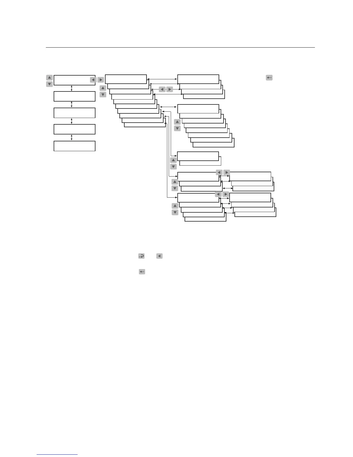
Fig. 4.2.1.2.-1 Monitoring measurements
To access the primary current values by activating the monitoring state:
1. Press
and simultaneously to view the primary line currents on phases I
a
,I
b
and I
c
and the ground-fault current, I
n
.
2. Press
to return the display to the idle mode.
The display has to be in the idle mode to be able to activate the monitoring state.
The display is not returned to the idle mode automatically as the monitoring state
does not have a time out. In case a fault is detected, however, the fault target
displaces the monitoring state.
Motor Protection Relay
Operator's Manual - ANSI ve rsion
REM 610REM 610
1MRS755538

 Loading...