6
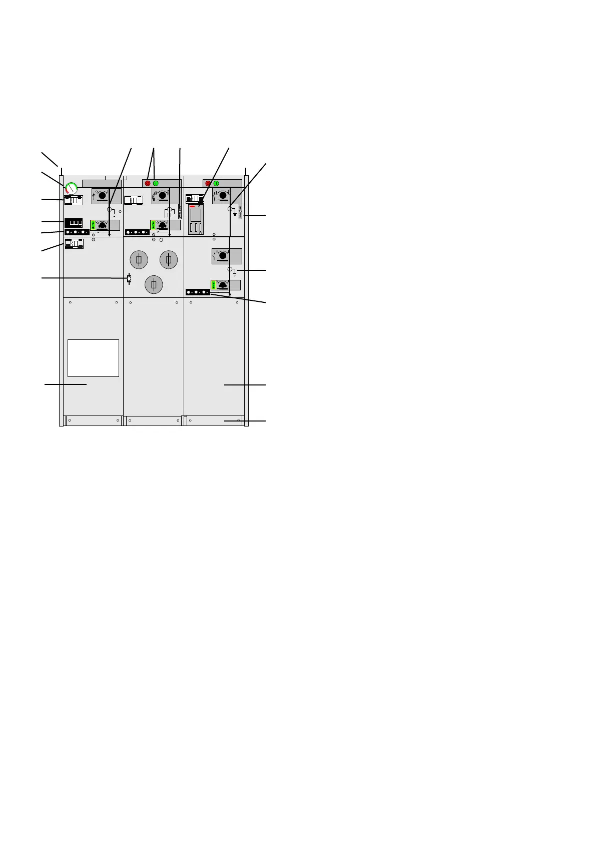
2.1 OUTER ASSEMBLY
Upper front cover
1. Manometer
2. Nameplate of module
3. Short circuit indicator
4. Capacitive voltage indication
5. Load break / earthing switch position indicator
6. Push buttons close/open operation
7. Charged spring indicator
8. Self-powered protection relay
9. Vacuum circuit-breaker position
Lower front cover
10. Nameplate of switchgear
11. Fuse blown indicator
12. Disconnector / earthing switch position indicator
13. Capacitive voltage indication
Cable compartment cover
14. Cable compartment cover standard
15. Cable compartment cover with inspection window
16. Support bar (removable)
Side cover
17. Lifting lug
18. Operating handle (suspended on the side wall, by
default on the right-hand side wall)
17
1
2
3
4
10
11
5
6 7 8
9
18
12
13
14
16
15
 Loading...