Interface Connector Pin Remark
Current phase L2+ X13 2
Current phase L3- X12 1
Current phase L3+ X12 2
Current phase N- X11 1
Current phase N+ X11 2
Optical network interface X101/X102
IEC/UCA 61850-9-2LE process bus/
system bus
X101 NA SFP cage for optional
100Base-FX SFP module
IEC/UCA 61850-9-2LE process bus/
system bus
X102 NA SFP cage for optional
100Base-FX SFP module
Electrical network interface X103/X104
IEC/UCA 61850-9-2LE process bus/
system bus
X103 NA 100Base-TX
IEC/UCA 61850-9-2LE process bus/
system bus
X104 NA 100Base-TX
Configuration interface X105
Connection to SAM600
configuration tool
X105 NA USB-A/USB-A cable
LED status indication D2
Status indications D2.1-D2.4 NA For more details refer
to Section 7.2.3
7.2.2.2 SAM600-VT
GUID-9F23E161-3BBF-468E-8468-F8FB7F00939B v1
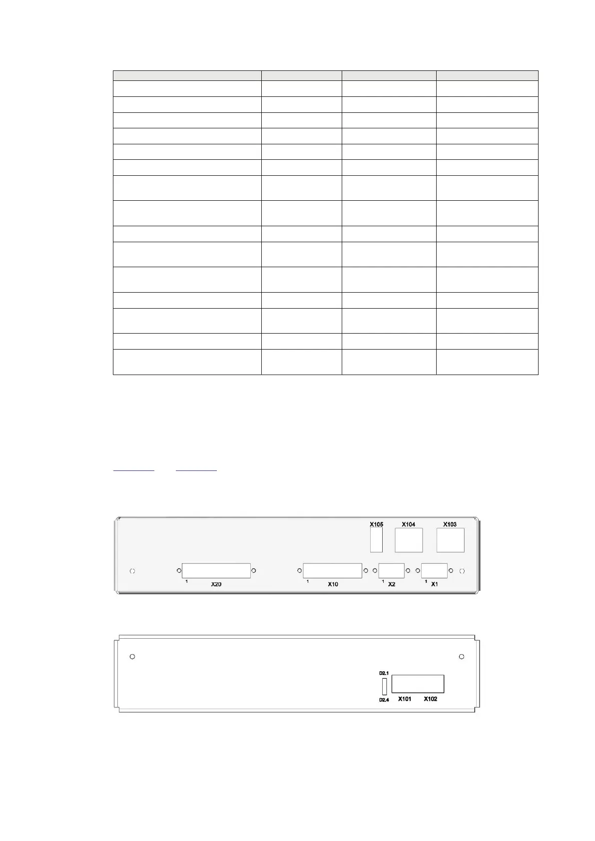
SAM600-VT has four voltage measurement channels and digital inputs for auxiliary signal
supervision. Those channels are accessible via the connectors X11 and X10, respectively.
Figure 18 and Figure 19 depict the position and numbering of connectors of the SAM600-VT
module.
Side plate connector positions
IEC18000528 V1 EN-US
Figure 18: SAM600-VT module electrical Ethernet side view
IEC18000529 V1 EN-US
Figure 19: SAM600-VT module fiber optical Ethernet side view
Section 7 1MRK 511 434-UEN B
Technical Data
42 SAM600 Process Bus I/O System
Operation Manual
© Copyright 2017 ABB. All rights reserved

 Loading...