Interface Connector Pin Remark
Configuration interface X105
Connection to SAM600
configuration tool
X105 NA USB-A/USB-A cable
LED status indication D2
Status indications D2.1-D2.4 NA For more details refer to
Section 7.2.3
7.2.2.3 SAM600-TS
GUID-32DE8A52-6540-44AA-AEB8-8D2212C47228 v1
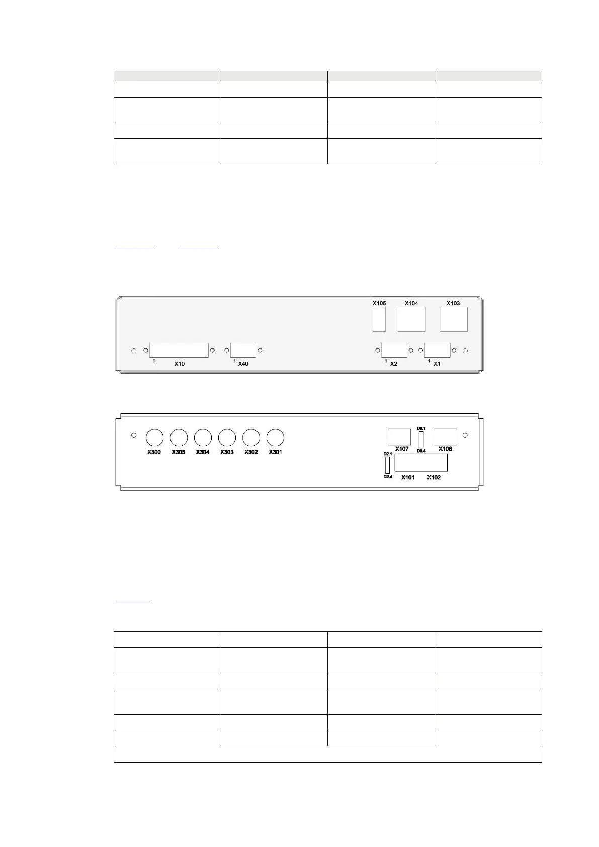
SAM600-TS has two additional optical SFP connectors and watchdog contacts.
Figure 20 and Figure 21 depict the position and numbering of connectors of the SAM600-TS
module.
Side plate connector positions
IEC18000530 V1 EN-US
Figure 20: SAM600-TS module electrical Ethernet side view
IEC18000531 V1 EN-US
Figure 21: SAM600-TS module fiber optical Ethernet side view
Wiring diagrams
Wiring diagrams for SAM600-TS can be found in document 1KHL511910.
Connector descriptions
Table 11 lists the interface descriptions for the SAM600-TS module.
Table 11: Interfaces for SAM600-TS
Interface
Connector Pin Remark
Power supply interface
(Not activated)
X1/X2
Power supply - VDC X1 1
Power supply +24 VDC
(main power)
X1 2
Power supply - VDC X1 3
Power supply - VDC X2 1
Table continues on next page
Section 7 1MRK 511 434-UEN B
Technical Data
44 SAM600 Process Bus I/O System
Operation Manual
© Copyright 2017 ABB. All rights reserved

 Loading...