8 SCC-C Sample Gas Cooler Operator’s Manual 42/23-55 EN Rev. 1
Dimensional Drawing
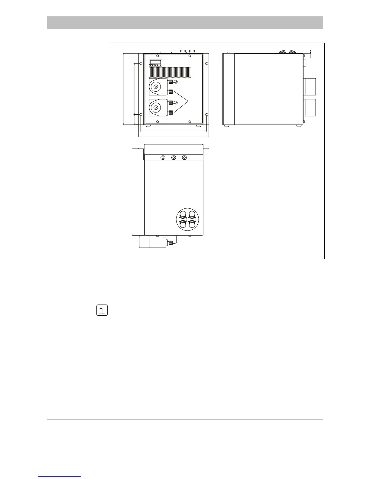
Fig. 1
Dimensional Drawing
(Dimensions in mm)
3.0
13
266
220
326.5
46
246
263
37.8 190.5
1
2
3
4
1 Temperature Controller
2 Condensate Outlet (in the Model with Peristaltic Pumps)
3 Heat Exchanger Sample Gas Connections
4 Passages for the (Fixed) Electrical Connection Cables
• You must take the additional space requirement into account
• Adjacent to the instrument on the right-hand side for the cooling air inlet, and
in front of the instrument for the cooling air outlet (approx. 10 cm in each case),
• in front of and underneath the instrument for connecting the condensate pipes
and
• above the instrument for connecting the sample gas lines and the electrical
leads.
• The fixing brackets are fitted in the factory, with about 2.5 cm projection to the
rear wall.
• Slope max. 5°.

 Loading...